Arc welder and torch for same

US6259059B1Inactive Publication Date: 2001-07-10LINCOLN GLOBAL INC

Image

  • Arc welder and torch for same
  • Arc welder and torch for same
  • Arc welder and torch for same

Examples


Embodiment Construction

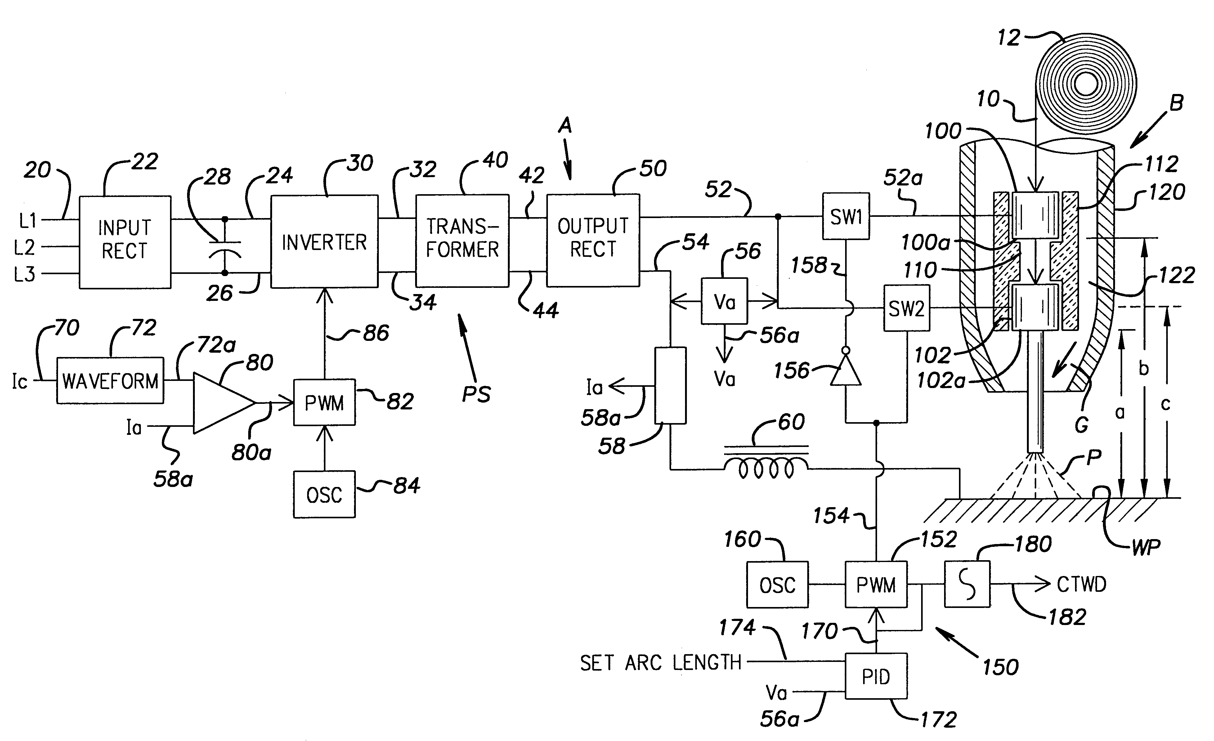
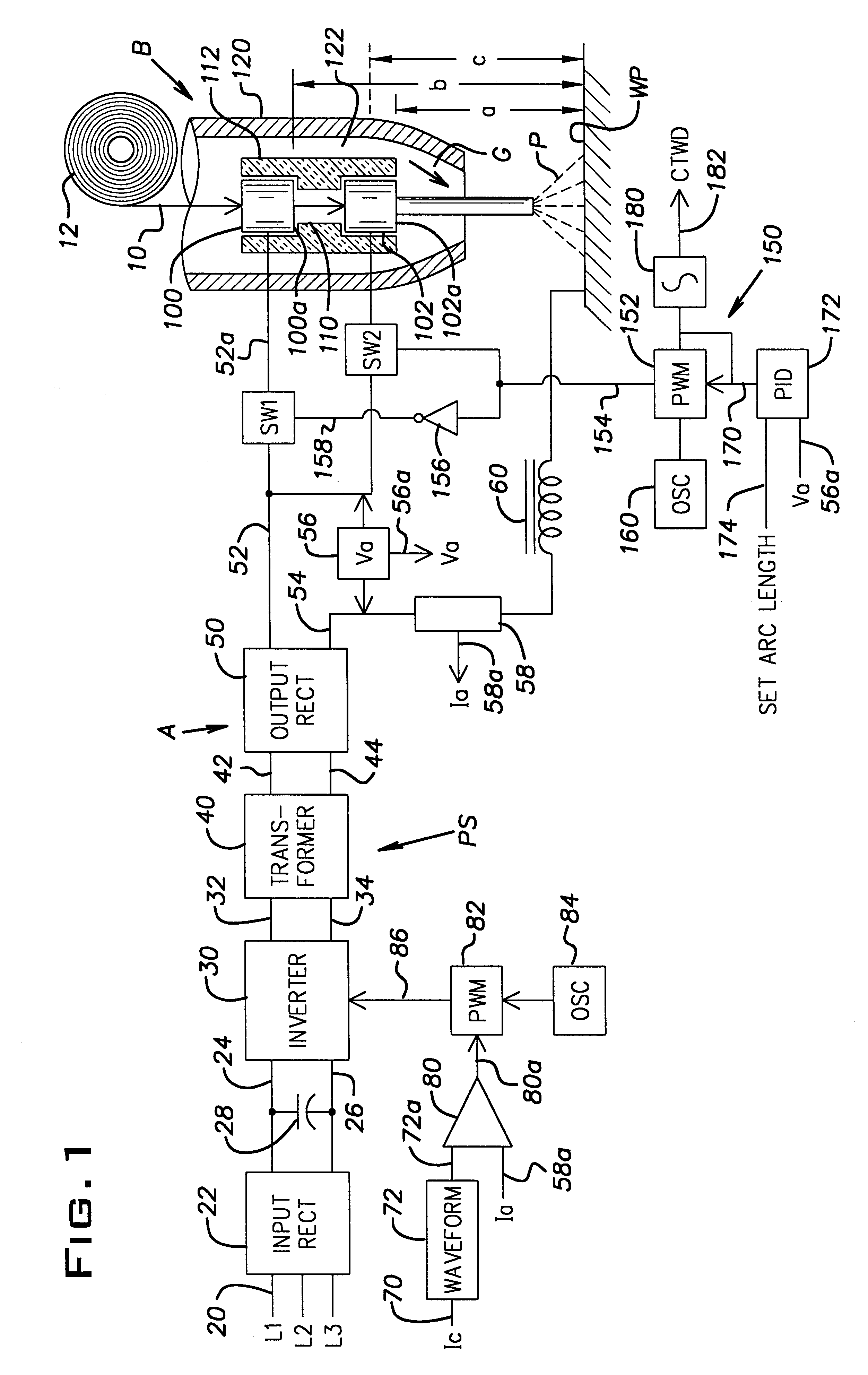
Referring to the drawings wherein the showings are for the purpose of illustrating a preferred embodiment of the invention only and not for the purpose of limiting same, FIG. 1 shows an electric arc welder A of the constant voltage type for providing weld current to torch or welding gun B so the torch can perform a welding operation. A consumable electrode or wire 10, supplied by a standard spool 12 and directed through the torch or gun B toward a workpiece WP, is melted at arc P. When the arc melts the end of wire 10 the molten metal is transferred to a weld bead on workpiece WP. Power supply PS is not a part of the invention and is arranged in accordance with somewhat standard architecture. In the illustrated invention it is an inverter unit; however, a traditional non-inverter power supply can be used. A three phase input 20 drives input rectifier 22 to produce a DC voltage across leads 24, 26 on opposite terminals of filter capacitor 28. A high speed switching type inverter 30 c...


PUM

PropertyMeasurementUnit
Timeaaaaaaaaaa
Timeaaaaaaaaaa
Frequencyaaaaaaaaaa

Abstract

In an electric arc welder for creating an arc welding process between a consumable electrode advancing through a contact tip and a workpiece, the welder including a power supply to create an arc current and arc voltage and having a first lead connected to the contact tip and a second lead connected to the workpiece, the improvement comprising dividing the contact tip into an upper tip section and a lower tip section with an insulator electrically isolating the sections, a first switch selectively shiftable to a conductive state connecting one of the power supply leads to said upper tip section, a second switch selectively shiftable to a conductive state connecting the one lead to the lower tip section and a switch operating network creating a first switch signal to shift the first switch to its conductive state and/or a second switch signal to shift the second switch to its conductive state to control the effective CTWD of the arc welding process.

Description

The present invention relates to the art of electric arc welding and more particularly to an arc welder and a unique welding torch for use in electric arc welding.BACKGROUND OF INVENTIONGas metal arc welding (GMAW) involves applying electrical current to a contact tip in a welding torch through which a consumable electrode or welding wire is passed as it moves toward a workpiece. Electrical current connected to the welding wire by the contact tip creates the electric arc for the welding process in accordance with standard welding technology. A power source, normally a high speed switching inverter, creates the welding current and is normally regulated on the basis of arc voltage to maintain a stable arc length in a constant voltage welding or pulse welding. The electrode or welding wire advancing through the contact tip toward the workpiece is electrically connected to the workpiece by the electric arc having a length that should have a given length for a specific process. The spaci...

Claims


Application Information

Patent Timeline
10 Jul 2001
Publication
US6259059B1
IPC
B23K9/06; B23K9/073; B23K9/09; B23K9/095; B23K9/10; B23K9/00; B23K9/26; B23K9/127; B23K9/29; H02M9/00
CPC
B23K9/0735; B23K9/092; B23K9/1062; B23K9/095; B23K9/093; B23K9/00
Inventors
HSU, CHRISTOPHER