
Digital optical joystick with mechanically magnified resolution

Inactive Publication Date: 2001-07-10
MEYERS NORMAN H
View PDF32 Cites 83 Cited by
  • Summary
  • Abstract
  • Description
  • Claims
  • Application Information

AI Technical Summary

Benefits of technology

3. Another object of this invention is to provide a joystick with improved linearity between angular rotation of the joystick shaft and the digital output readings.
4. A further object of this invention is to incorporate all electronic functions into a single, low cost, commercially available microcomputer in such a way that the possibility of failing to count some very rapid encoder pulses, or some pulses arriving simultaneously from multiple axes, is greatly reduced.

Problems solved by technology

Most of these joysticks are able to sense the motion of the shaft in one of four or eight different radial directions but do not sense how far the shaft has moved in the chosen direction.
However, the digital resolution is exceedingly low (one binary bit of information for each of the eight detectable directions of shaft motion).
Also, the electrical contacts in mechanically operated switches are subject to wear, corrosion, contamination, pitting, and contact bounce.
Joysticks of this type lack the resolution and reliability needed for control of powered wheelchairs, fork lifts, machine tools, earth-moving machines, robotic devices, etc.
In each case of this type, the resolution achievable increases with the number of contacts employed but the joystick becomes mechanically complex if high resolution is needed.
Furthermore, the reliability of the joystick decreases and the cost increases as the number of contacts is raised to improve resolution.
Another disadvantage of this prior art device (Lantz et al.) is that it includes, along with some other prior art devices, an inherent source of non-linearity due to its conversion of shaft rotation to rectilinear motion of plates transporting the encoded medium.
These approaches are more reliable than resistive potentiometers but are inherently non-linear (i.e., unlike resistive potentiometers which are normally fabricated to be very linear, the analog output signal from these inductive devices does not vary linearly with joystick shaft position).
Electronic compensation of this inherent non-linearity is feasible but adds to cost and complexity.
The analog joysticks employing optoelectronic devices suffer from the same drawbacks as the inductive devices just described.
Hence, the complexity, size, and cost rise rapidly as the resolution increases and absolute encoders generally have not been exploited for joystick applications.
Note, however, that the device described earlier as disclosed in U.S. Pat. No. 4,856,785 (Lantz et al.) can be viewed as a joystick employing absolute optical encoding but with relatively low resolution.
A limitation of this third track approach is that there is no absolute position information available until the counter has received the clear or preset pulse the first time.
Thus, when power first comes on, the counter might be reading anything and the joystick shaft might be anywhere and, therefore, no position information is available.
This is unacceptable in many joystick applications; a powered wheelchair, for example, because the chair could "take off" with arbitrary direction and speed when first powered up.
But, in many cases (the power chair case, for example), there can be no such guarantee.
Therefore, the application of incremental optical encoding to a joystick requires a fail-safe means of converting the incrementally encoded signals into absolute position information.
This patent does not disclose any method for converting the incrementally encoded signals into absolute position information, a requirement in most practical applications of a joystick.
Note also that the resolution provided by the method disclosed, while potentially very high, is limited by the density of the pattern encoded on the film and the ability of the optical components to read that pattern correctly.
The parallel port of the microcomputer, which receives all of the input signals from the encoders in Geller's disclosure, is level sensitive rather than edge sensitive and can not retain the fact that a pulse occurred on one or more of its bit lines.
However, a joystick employing incremental optical encoding that is slammed rapidly from neutral to full scale along both axes at once can lose a number of counts if the method of the referenced patent is used.
The ASIC approach, while powerful and potentially very fast, has a very high development cost that can be justified only in a very high volume application.

Method used


Image

  • Digital optical joystick with mechanically magnified resolution
  • Digital optical joystick with mechanically magnified resolution
  • Digital optical joystick with mechanically magnified resolution

Examples


Embodiment Construction

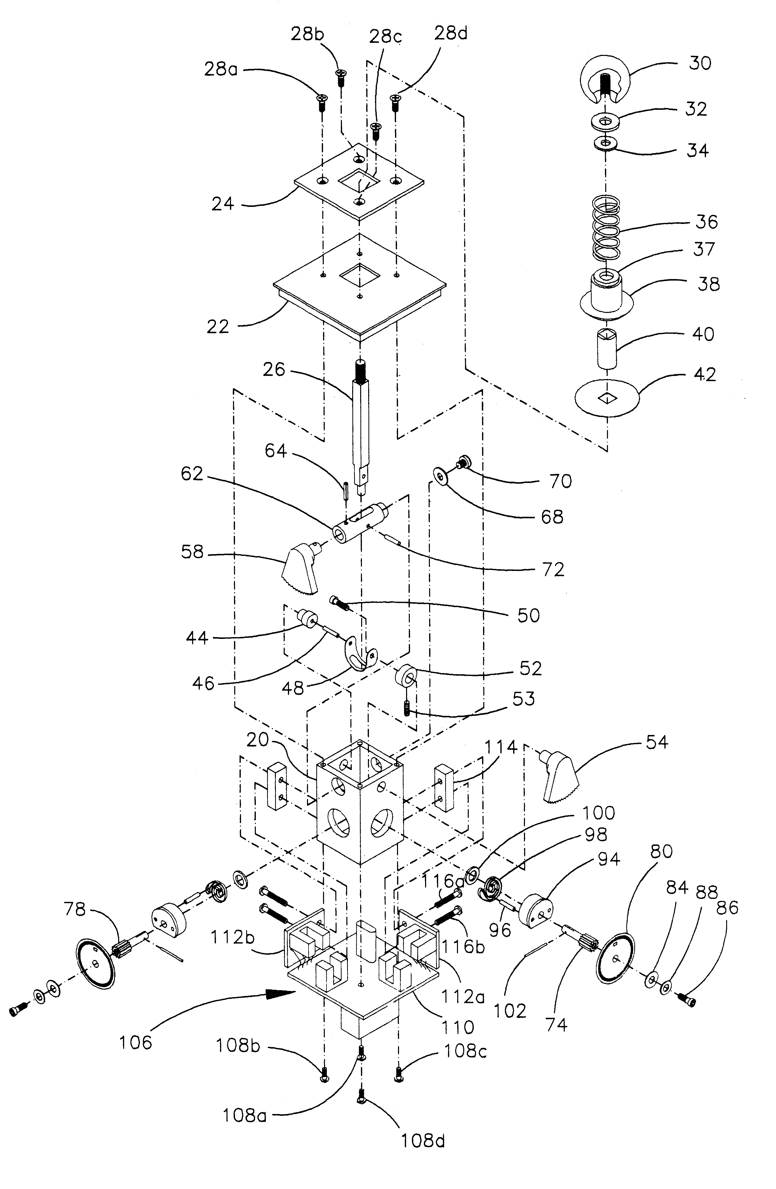
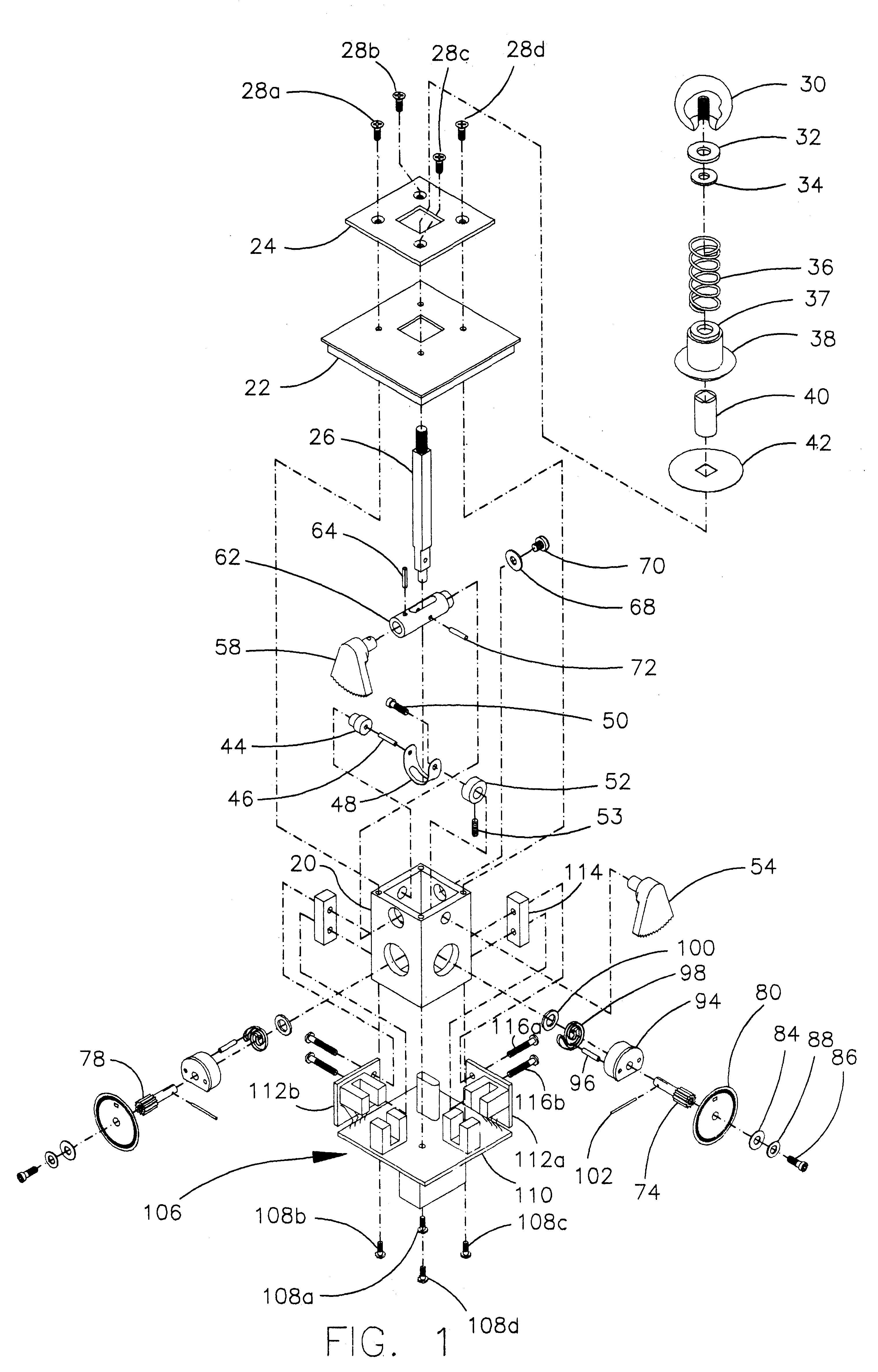
FIG. 1 shows an exploded view of a preferred embodiment of the present invention. A hollow square tube 20 with a number of holes in it serves as a central supporting structure for the entire joystick. Tube 20 can be made of aluminum or other metal with holes machined in it or of a suitable plastic such as nylon with holes molded in place. A lid 22 and a stop plate 24, that limits the angular travel of a shaft 26, are atop tube 20 and attached to it by flat head screws 28a, 28b, 28c, and 28d. A mechanism for restoring shaft 26 to its neutral (vertical) position consists of a threaded knob 30, a bearing washer 32, a centering washer 34, a compression spring 36, a cam 38 with a curved base, a self-lubricating bearing 40 that is pressed into cam 38, and a thin disc 42 of some smooth easy sliding material such as teflon. The upper end of shaft 26 passes through the square openings of lid 22 and stop plate 24 and then through all the elements of the restoring mechanism and finally threads...


PUM


Abstract

A one or multiple axis digital joystick using incremental optical encoding with mechanical means for magnifying motion of the encoded medium to achieve higher resolution than otherwise attainable with the same optoelectronic components. Excellent linearity between shaft rotation and digital output results from elimination of backlash and preservation of rotary-only motion in the mechanical linkage between shaft and encoder disc. All electronic functions are implemented in a low-cost internal microcomputer that interfaces in serial or parallel mode with many system computers or microcomputers without additional circuitry. The microcomputer converts the incrementally encoded signals from the optoelectronic devices into absolute shaft-position information in a fail-safe manner. The joystick can be operated very rapidly without error because the encoded pulses to be counted are applied to microcomputer inputs that store the occurrence of each pulse until the microcomputer can process them. The stored program also ensures that each joystick has the same full-scale outputs despite minor mechanical variations from one joystick to another. In addition, it corrects errors caused by hysteresis in some of the optoelectronic components. The resulting joystick is field replaceable without any adjustments or recalibration.

Description

1. Field of InventionThis invention relates to a one or multiple axis joystick that uses incremental optical encoding and the principle of mechanical advantage to obtain a digital output of enhanced resolution that is a reliable measure of absolute shaft position and which can be read by a computer without interface circuitry.2. Description of Prior ArtThere is much prior art related to the use of joysticks as man-to-machine input devices. A variety of joysticks have been used to input commands to video game controllers or to control the motion of a cursor on a video screen. Examples include U.S. Pat. No. 4,488,017 (Lee) and U.S. Pat. No. 4,501,939 (Hyltin et al). Devices of this type employ electrical contacts or switches which are actuated by motion of the joystick shaft. Most of these joysticks are able to sense the motion of the shaft in one of four or eight different radial directions but do not sense how far the shaft has moved in the chosen direction. The output signal is dig...

Claims


Application Information

Patent Timeline
IPC IPC(8): G05G9/047G05G9/00
CPCG05G9/047G05G2009/04759G05G2009/04748
Inventor MEYERS, NORMAN H.
Owner MEYERS NORMAN H
Learn More