Real-time mission adaptable route planner

a real-time mission and planner technology, applied in the direction of navigation instruments, instruments, energy saving arrangements, etc., can solve the problems of increasing the likelihood of human error in planning by a navigator including responses to changes in conditions or circumstances, and the inability of highly trained navigators to assimilate the amount of information which may be available,

Inactive Publication Date: 2001-07-10
LOCKHEED MARTIN CORP
View PDF16 Cites 289 Cited by
  • Summary
  • Abstract
  • Description
  • Claims
  • Application Information

AI Technical Summary

Problems solved by technology

While greater availability of information has improved safety and efficiency of route choice, even highly trained navigators are unable to assimilate the amount of information which may be available or to assign an appropriate degree of importance to each item of information and are thus able to perform only the most rudimentary of quantitative optimization of route details.
Further, planning by a navigator including responses to changes of conditions or circumstances is always subject to human error; the likelihood of which increases with the amount of information available for consideration.
Additionally, in recent years, many more types of information and constraints have been included in route planning which further complicates the route planning process for a human navigator.
However, grid-based techniques can accommodate quantitative metrics and limits and particular constraints only with difficulty and a solution complying therewith may not be found.
Further, discontinuities in the search space may not allow some solutions to be reliably f...

Method used


Image

  • Real-time mission adaptable route planner
  • Real-time mission adaptable route planner
  • Real-time mission adaptable route planner

Examples


Embodiment Construction

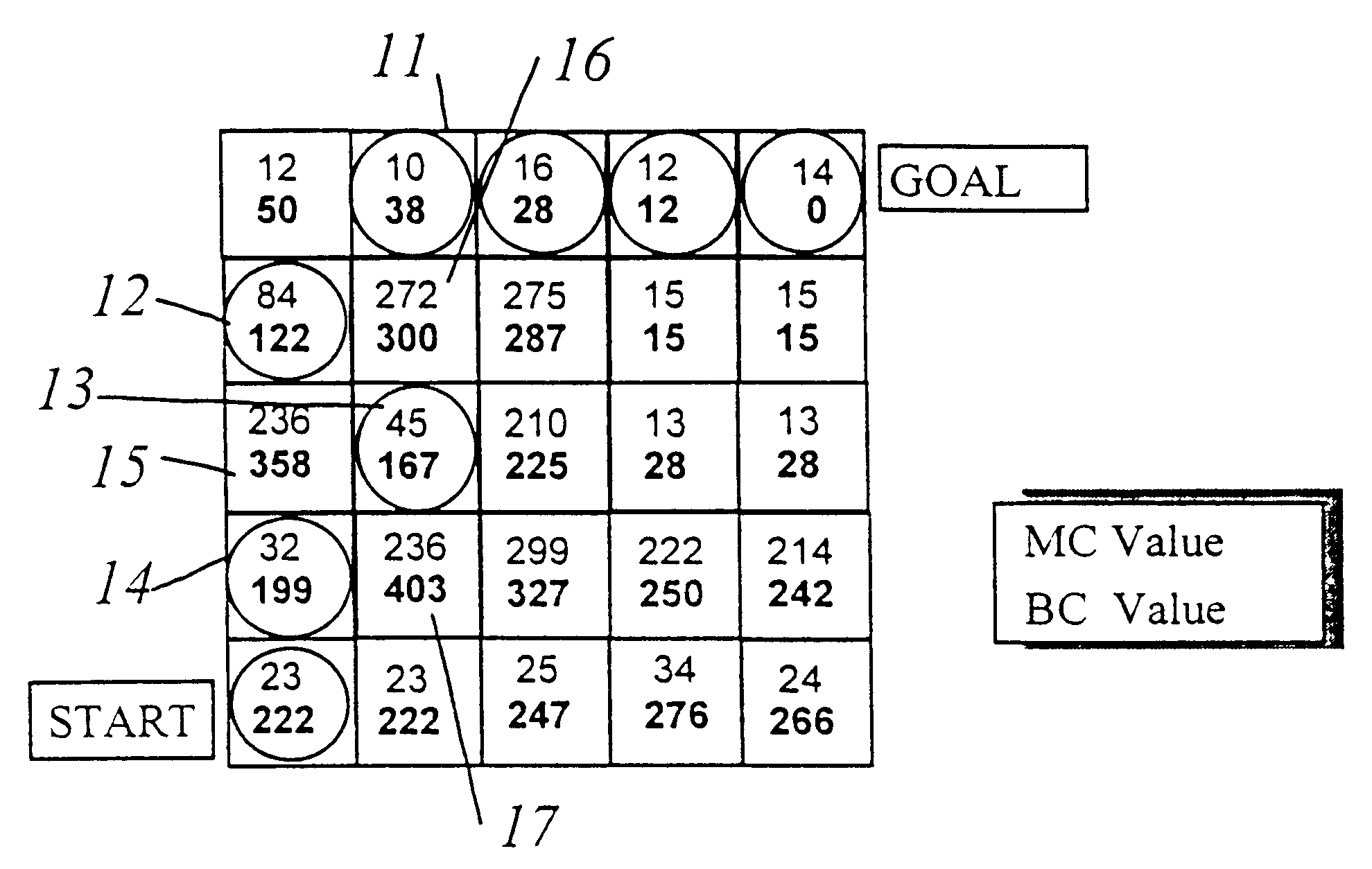
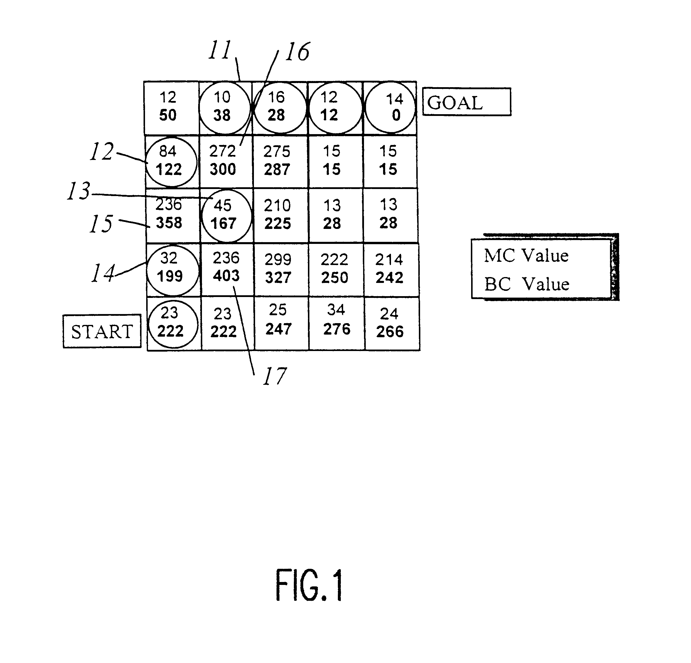
Referring now to the drawings, and more particularly to FIG. 1, there is shown a graphical depiction of a grid-based methodology for finding a solution to an optimization problem such as a route plan to which the invention is preferably applied, possibly with variations which will be evident to those skilled in the art in light of the following description of the invention. Many such grid-based methodologies are known and some may duplicate the results illustrated in FIG. 1. By the same token, the methodology depicted in FIG. 1 is performed initially to provide inputs for the system and remainder of the methodology of the invention and other grid-based systems presently known may be equally suitable for that limited purpose within the context of the invention. However, it is to be understood that FIG. 1 depicts a preferred methodology for developing input information for the system and methodology in accordance with the invention and the inclusion of a grid-based system forms a part...


PUM


Abstract

A hybrid of grid-based and graph-based search computations, together with provision of a sparse search technique effectively limited to high-probability candidate nodes provides accommodation of path constraints in an optimization search problem in substantially real-time with limited computational resources and memory. A grid of best cost (BC) values are computed from a grid of map cost (MC) values and used to evaluate nodes included in the search. Minimum segment/vector length, maximum turn angle, and maximum path length along a search path are used to limit the number of search vectors generated in the sparse search. A min-heap is preferably used as a comparison engine to compare cost values of a plurality of nodes to accumulate candidate nodes for expansion and determine which node at the terminus of a partial search path provides the greatest likelihood of being included in a near-optimal complete solution, allowing the search to effectively jump between branches to carry out further expansion of a node without retracing portions of the search path. Capacity of the comparison engine can be limited in the interest of expediting of processing and values may be excluded or discarded therefrom. Other constraints such as approach trajectory are accommodated by altering MC and BC values in a pattern or in accordance with a function of a parameter such as altitude or by testing of the search path previously traversed.

Description

1. Field of the InventionThe present invention generally relates to navigation and planning optimization systems and, more particularly, to route planning for travel paths subject to a variety of navigational constraints.2. Description of the Prior ArtWhen a course of travel is not constrained by roads or other fixed structures, such as during travel by air or water or over unimproved land, careful navigation along a path extending from a starting point to a goal is required. The choice of a path may, in such a case, be constrained by many factors such as range or other physical limitations of a vehicle, weather conditions and other conditions which may compromise safety, and human factors, such as operator (e.g. pilot) workload. Some fixed structures may also affect the choice of path such as the orientation of a runway, the physical layout of harbors, docks and the like as well as physical obstacles which may be man-made or natural.In the past, a trained navigator (generally a pil...

Claims


Application Information

Patent Timeline
IPC IPC(8): G01C21/00
CPCG01C21/00G08G5/0034G06Q30/0284G06Q30/0283G05D1/0005G01C21/20G01C21/3881
Inventor GALKOWSKI, PEGGY J.GLICKSTEIN, IRA S.STILES, PETER N.SZCZERBA, ROBERT J.
Owner LOCKHEED MARTIN CORP
Why Eureka
Try Eureka