Terminal contact-type IC card having terminal contact fault detector, IC card system using the IC card, and IC for the IC card
a terminal contact and fault detector technology, applied in the direction of individual semiconductor device testing, direction of current indication, instruments, etc., can solve the problems of degrading the reliability of the ic card, degrading the contact failure at the terminal, and the inability of the reader-writer to properly and quickly cope with the faul
- Summary
- Abstract
- Description
- Claims
- Application Information
AI Technical Summary
Problems solved by technology
Method used
Image
Examples
first embodiment
(First embodiment)
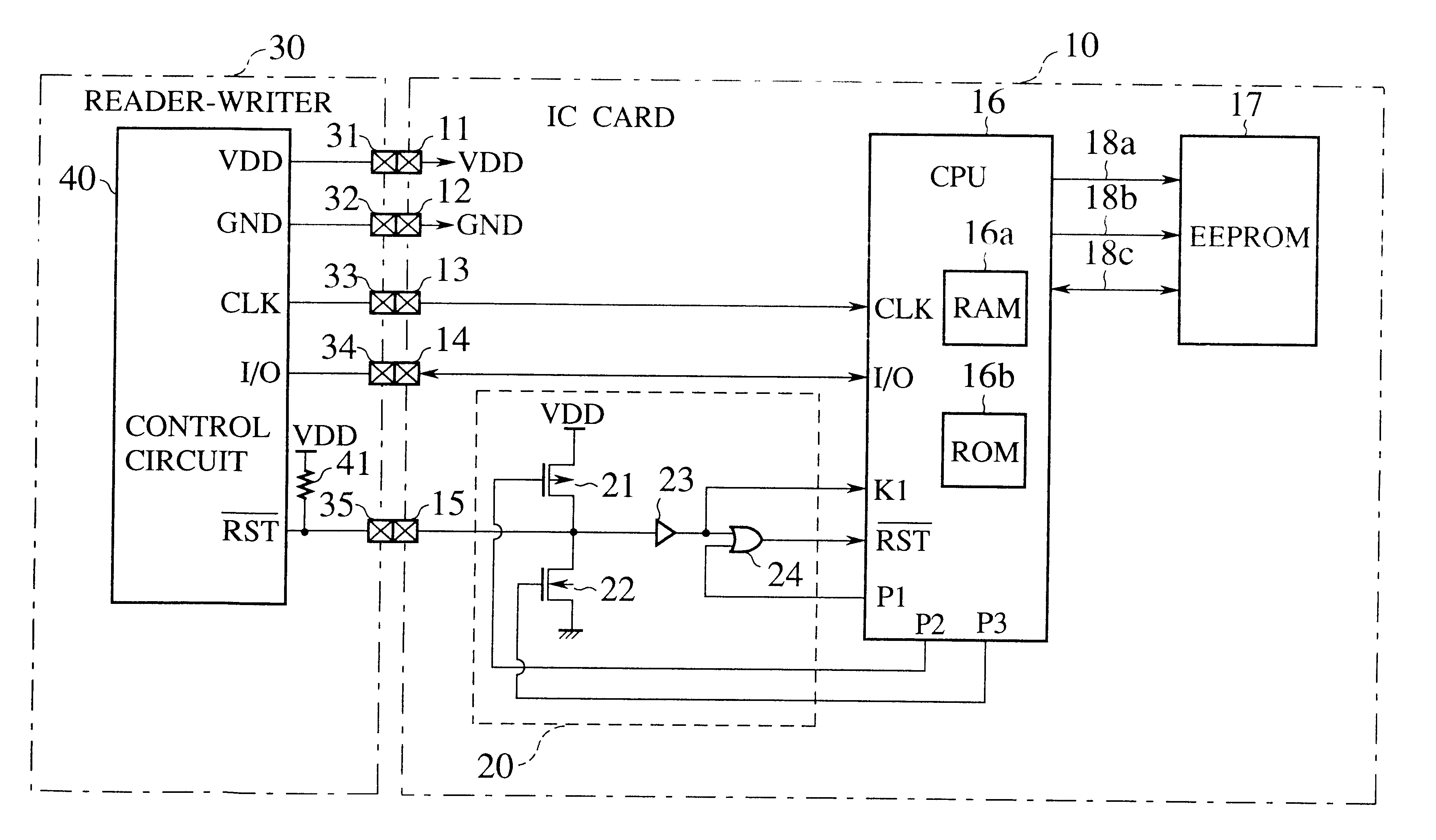
FIG. 3 is a block diagram showing a contact-type IC card system according to the first embodiment of the present invention. The system includes a contact-type IC card 10 and a reader-writer 30. The reader-writer 30 mediates between the IC card 10 and a host computer (not shown). The IC card 10 has a first set of terminals exposed outside. The first set of terminals include a terminal 11 for receiving a supply voltage VDD, a terminal 12 for grounding, a clock terminal 13 for receiving a clock signal CLK, an I / O terminal 14 for communicating data, and a reset terminal 15 for receiving a reset signal RST. The IC card 10 incorporates a single semiconductor chip monolithically integrating a CPU 16, an EEPROM 17, an address bus 18a, a control bus 18b, and a data bus 18c. These buses connect the CPU 16 and EEPROM 17 to each other. The CPU 16 has a RAM 16a serving as a work area and a ROM 16b for storing programs. The CPU 16 controls an interface with the reader-writer 30 ...
second embodiment
(Second embodiment)
FIG. 6 is a block diagram showing a contact-type IC card system according to the second embodiment of the present invention. The system includes a contact-type IC card 50, a reader-writer 30 serving as an external unit, and a host computer (not shown). The IC card 50 has a first set of terminals including a terminal 11 for receiving a supply voltage VDD, a terminal 12 for grounding, a clock terminal 13 for receiving a clock signal CLK, an I / O terminal 14, and a reset terminal 15 for receiving a reset signal RST. The reader-writer 30 has a second set of terminals 31 to 35. The IC card 50 incorporates a semiconductor IC chip monolithically integrating a CPU 56, a peripheral circuit, a detector 60, and a self-oscillator 67. The CPU 56 includes a RAM 56a and a ROM 56b. The peripheral circuit includes an EEPROM 17. The CPU 56 and EEPROM 17 are connected to each other through buses 18a, 18b, and 18c.
The CPU 56 has a testing function and a controlling function that are c...
third embodiment
(Third embodiment)
FIG. 10 is a flowchart showing the operation of a contact-type IC card system according to the third embodiment of the present invention. The hardware of the third embodiment is the same as that of the second embodiment of FIG. 6. Namely, the system employs the TC card having the single semiconductor IC chip containing the CPU 56, EEPROM 17, detector 60, and self-oscillator 67. The third embodiment is characterized in that, if the contact condition of the clock terminal 13 is determined to be poor and faulty while data is being written into a given area of the EEPROM 17, an abnormality identifier is written into the area in question, so that it is easily recognized that the data in the area is erroneous when it is read out of the EEPROM 17.
After step S31 in FIG. 10, step S41 checks to see if data is being written into the EEPROM 17. If so, step S42 writes an abnormality identifier ED into a part of, for example, a record R1 as shown in FIG. 11. Thereafter, step S34...
PUM
 Abstract
Description
Claims
Application Information
 - R&D
- Intellectual Property
- Life Sciences
- Materials
- Tech Scout
- Unparalleled Data Quality
- Higher Quality Content
- 60% Fewer Hallucinations
Browse by: Latest US Patents, China's latest patents, Technical Efficacy Thesaurus, Application Domain, Technology Topic, Popular Technical Reports.
© 2025 PatSnap. All rights reserved.Legal|Privacy policy|Modern Slavery Act Transparency Statement|Sitemap|About US| Contact US: help@patsnap.com


