Drilling system with downhole apparatus for determining parameters of interest and for adjusting drilling direction in response thereto

a drilling system and downhole technology, applied in the field of drilling systems, can solve the problems of limiting the ability to transmit a vast amount of useful information about the formation of downholes and the conditions of downholes to the surface during drilling operations, and high cos

Inactive Publication Date: 2001-08-07
BAKER HUGHES INC
View PDF2 Cites 317 Cited by
  • Summary
  • Abstract
  • Description
  • Claims
  • Application Information

AI Technical Summary

Problems solved by technology

Stopping the drilling operation and retrieving the drill string to adjust the drilling direction results in great expense.
Surface-measured depth readings rely on the drill pipe length, which over several thousand feet may have an error of several feet (15 to 50 feet) from the true location, which is highly undesirable, especially for horizontal drilling through relatively narrow formations.
The current telemetry systems such as the mud-pulse telemetry systems are capable of transmitting typically one bit per second, which greatly limits the ability to transmit a vast amount of useful information about the downhole formations and downhole conditions to the surface during the drilling operation.
All of the aforementioned sensors used in the wireline tools are data intensive.
When such measurements are made simultaneously with a single pass of a multiple sensor wireline device along the borehole, massive amounts of raw data are generated per depth interval of borehole traversed.
Simultaneous measurements using multiple, data-intensive sensors can generate amounts of raw data which exceed the telemetry capacities of single conductor wireline systems.
As a result, the raw data is sometimes compressed before being telemetered to the surface, which results in a loss of vertical resolution of the measurements and / or a degradation in accuracy of the measurements.
However, such wireline correlations often do not reveal critical structural aspects of the field as will be illustrated and further discussed in subsequent sections of this disclosure.
The spatial resolution of seismic measurements is poor when compared to wireline measurements.
Although well log and seismic correlations are used to select locations and target zones of development wells, poor spatial resolution presents a problem in defining the target formation with the accuracy and precision required by the driller.
Thus, there is a great need to determine various parameters of interest downhole during the drilling of boreholes because massive data generated by the sensors cannot be transmitted uphole during the drilling operation.
Logging after completion of the drilling operation often reveals that the target formation or formations have been missed.
In addition, unexpected zones such as high pressure formations or salt zones, can be encountered during the drilling operation.
These formations and zones can add costly delays to the drilling operation and endanger drilling personnel and equipment.
Also, damage to the borehole can occur during logging and drilling rig time and logging equipment time is wasted during stand-by periods for each operation.
These MWD systems provided directional information and a limited number of formation evaluation type measurements.
Current MWD systems do not combine multiple sensor measurements because current MWD telemetry does not have the capacity to simultaneously transmit a plurality of full acoustic wave forms or gamma ray energy spectra or electromagnetic wave attenuation and phase shift data, or a combination thereof, to the surface for processing to determine parameters of interest at intervals sufficient to obtain the required vertical resolution of the penetrated formations.
Furthermore, it is not feasible to store copious amounts of raw downhole sensor data for subsequent retrieval and processing due to relatively limited storage capacity of current MWD systems.
It is not feasible to make such measurements using wireline technology because of operational, technical and costs constraints.

Method used


Image

  • Drilling system with downhole apparatus for determining parameters of interest and for adjusting drilling direction in response thereto
  • Drilling system with downhole apparatus for determining parameters of interest and for adjusting drilling direction in response thereto
  • Drilling system with downhole apparatus for determining parameters of interest and for adjusting drilling direction in response thereto

Examples


Embodiment Construction

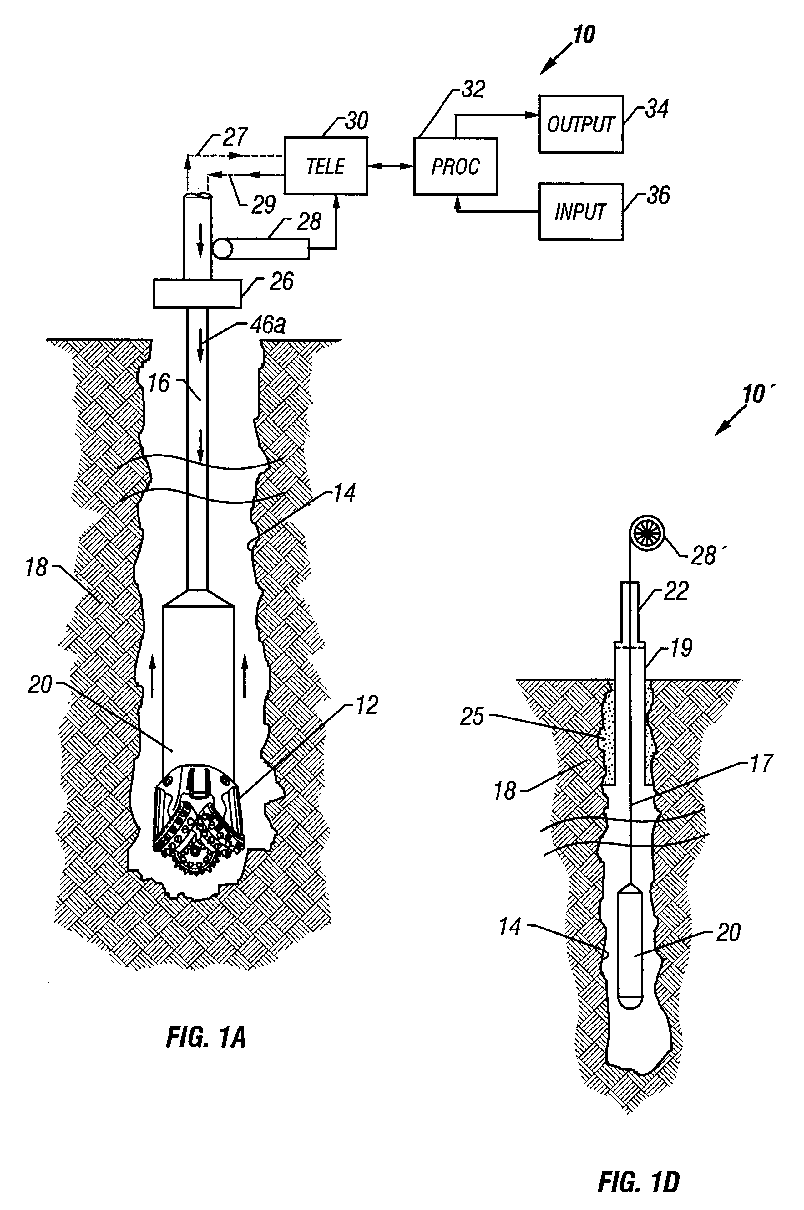
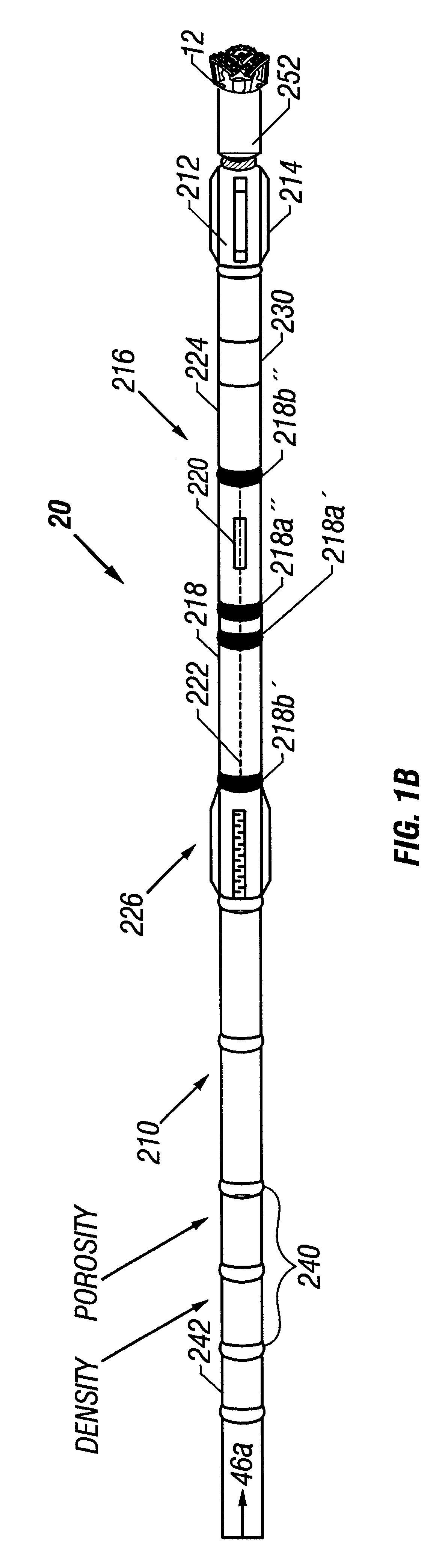
FIG. 1a shows a schematic diagram of a measurement-while-drilling (MWD) embodiment of the system 10 of the present invention. It includes a downhole subassembly 20 that is suspended within the borehole 14 by a drill string 16 during drilling of the borehole 14. The downhole subassembly 20 is positioned as close as practical to the drill bit 12. The drill bit 12 is rotated by a downhole motor contained in the downhole subassembly and / or by rotating the drill string by a surface prime mover to drill the borehole 14 in the earth formation 18. For simplicity, the prime mover and other components of the surface drilling rig are not shown. A preferred embodiment of the downhole assembly 20 comprising various sensors and devices will be described later with reference to FIGS. 1b and 1c.

Data from the downhole subassembly 20 are telemetered by a downhole telemetry system (not shown) in the downhole subassembly 20 to an uphole telemetry element 30. The uplink data telemetry path is indicated ...


PUM


Abstract

The present invention provides a measurement-while-drilling (MWD) system having a downhole computer and multiple downhole sensors. Relatively large amounts of basic or "raw" data are measured by downhole sensors, and these data are processed within a downhole computer to be reduced to parameters of interest, which may be utilized to control the drilling operation by downhole devices, stored downhole, telemetered to the surface, or both. The measurements may be correlated downhole with stored reference data thereby providing additional information pertaining to the drilling operation. Downhole depth correlation between downhole measured parameters may be made by utilizing surface determined or downhole determined borehole depth.

Description

1. Field of the InventionThe present invention relates generally to drilling systems and more particularly to a system of drilling boreholes having a measurement-while-drilling ("MWD") system wherein drilling and formation data and parameters determined from various downhole measuring devices are transformed downhole into selected parameters of interest or "answers" which are telemetered to the surface or stored downhole for subsequent retrieval or both. In an alternate embodiment, measurements are depth-correlated, utilizing depth measurements made downhole for improving accuracy of the measurements and the parameters of interest. The measurements and / or parameters are also correlated with stored reference data for providing additional information pertaining to the drilling operations and the formation characteristics. The system also is adapted to determine the drill bit location relative to the desired drilling path and to adjust the drilling activity downhole based on such deter...

Claims


Application Information

Patent Timeline
Patent Type & Authority Patents(United States)
IPC IPC(8): E21B7/04E21B47/12E21B7/06E21B44/00E21B47/022E21B47/02G01V11/00
CPCE21B7/068E21B44/005G01V11/00E21B47/124E21B47/022E21B47/26
Inventor WISLER, MACMILLAN H.MEYER, WALLACE H.MINETTE, DANIELDEADY, RONALDLEGGETT, III, JAMES V.BEIMGRABEN, HERBERT W.HUBNER, BERNARD G.
Owner BAKER HUGHES INC
Why Eureka
Try Eureka