
High speed digital zone control

a digital zone control and high-speed technology, applied in the field of display device alignment correction and alignment, can solve the problems of high resolution signal, system less economic attractiveness, and large amount of data storag

Inactive Publication Date: 2001-08-28
DISPLAY LAB
View PDF66 Cites 9 Cited by
  • Summary
  • Abstract
  • Description
  • Claims
  • Application Information

AI Technical Summary

Benefits of technology

The advantages of the present invention are that zone correction values can be generated as they are needed in both the horizontal and vertical directions. In other words, incremental correction values can be generated, utilizing the present invention, at a rate which is as fast as the pixel rate for high frequency monitors. Additionally, since the correction values are mapped to specific physical locations on the screen, the location and size of the video image on the screen can be moved without the necessity of determining an entirely new set of correction values for the entire screen. The present invention uses the correction values for the portion of the screen on which the video image is being displayed by generating zone correction values from group correction values that are tied to specified physical locations on the screen.
The present invention uses a fixed number of correction values that are tied to fixed physical locations on the screen. Additionally, the fixed number of physical divisions between group addresses is selected such that the number (a binary order of magnitude number) is readily divisible into the difference correction values in binary format. For example, the number of physical divisions between each group address is selected so that the division can be performed by merely shifting the decimal position of the difference correction values. Stated differently, a binary fractional multiplication can be employed by multiplying the difference correction value by a binary fractional number. This significantly increases the speed at which the divisions (or multiplications) can be performed to obtain the incremental correction values.
Since the correction values are mapped to specific physical locations on the screen, the present invention is able to determine the location of the video image on the screen and generate correction values for only that portion of the screen that is being used. In this manner, the present invention uses a fixed address space for the correction values and varies the starting point at which interpolated correction values are calculated based upon the location of the image on the screen. The present invention is also capable of handling an arbitrary number of scan lines or scan frequencies since the present invention generates zone correction values for the spatially fixed physical divisions, and then maps the zone correction values to the scan lines of the image. In other words, the present invention determines the physical location of the video signal or raster on the display and generates a binary start signal at the segment closest to the physical location of the video image or raster on the screen. A binary order of magnitude number of physical divisions are selected between each group address for each correction factor parameter so that quotient values can readily be generated by shifting the decimal position of the difference correction values. The binary fractional address of the physical divisions are used to generate incremental correction values.
Additionally, by tying the correction values to physical locations on the display screen, the resolution of the image remains constant for variations of the image size. Consistent resolution is therefore achieved and unnecessary computations, that slow the alignment procedure, are eliminated.
These features of the present invention greatly reduce the cost of the implementation of high resolution correction waveforms to provide a precisely aligned image.

Problems solved by technology

However, the generation of these correction waveforms using digital techniques requires the storage of a large amount of data in the form of correction values.
As the desire for enhanced resolution of these correction waveforms increases, the storage requirements cause these systems to be less economically attractive.
Additionally, certain correction factor parameters naturally require a very high resolution signal that necessitates a very large amount of correction value data.
To date, it has been uneconomical to provide digitally generated correction waveforms for these correction factor parameters.
However, difficulties have been encountered in providing satisfactory interpolation devices.
Typical interpolation engines use microprocessors or digital signal processors that are both expensive and normally too slow to process the interpolated correction values at the speed required to provide the interpolated data at the proper time.
Hence, the many different techniques that have been proposed have generally not been implemented in a satisfactory fashion because of these limitations.
Typical digital signal processors and microprocessors, however, are unable, in many instances, to generate these correction values fast enough to make corrections as the image is generated.
The inability of microprocessors and digital signal processors to provide interpolated correction values fast enough is the result of the number of high-speed divisions that must be performed by these devices.
These devices are not designed to perform high speed complex divisions and, as a result, are not able to provide the interpolated data as rapidly as it is needed.
Since only a portion of those values that are calculated are used, because the image only covers a portion of the screen, numerous calculations are made that are not necessary, which wastes valuable processing time which, in turn, limits the data that can be generated.
Variations in resolution with image size results in a further waste of computing time.

Method used


Image

  • High speed digital zone control
  • High speed digital zone control
  • High speed digital zone control

Examples


Embodiment Construction

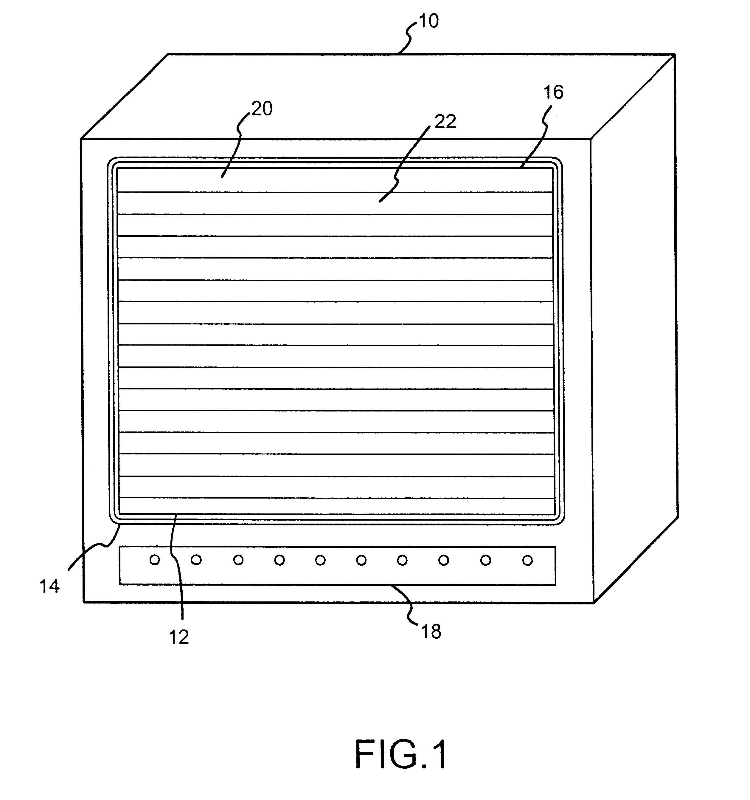
FIG. 1 is a schematic illustration of a raster scanned display 10 that has a video screen 12 mounted inside a bezel 14. A video image 16 is projected onto the screen 12. User controls 18 control parameters such as the horizontal and vertical size and centering of the video image 16 on screen 12, as well as the various corrections for both horizontal and vertical geometries. As shown in FIG. 1, the video image is divided into a plurality of groups 20, 22, etc. as indicated by the horizontal lines on the video image 16. These groups, which are divided by the horizontal lines as illustrated in FIG. 1, identify specific physical locations for generating group correction values that are used for corrections in the vertical direction. The raster scanned display can comprise any one of a number of different types of displays including CRT's, projected light or laser beams, holograms, etc.

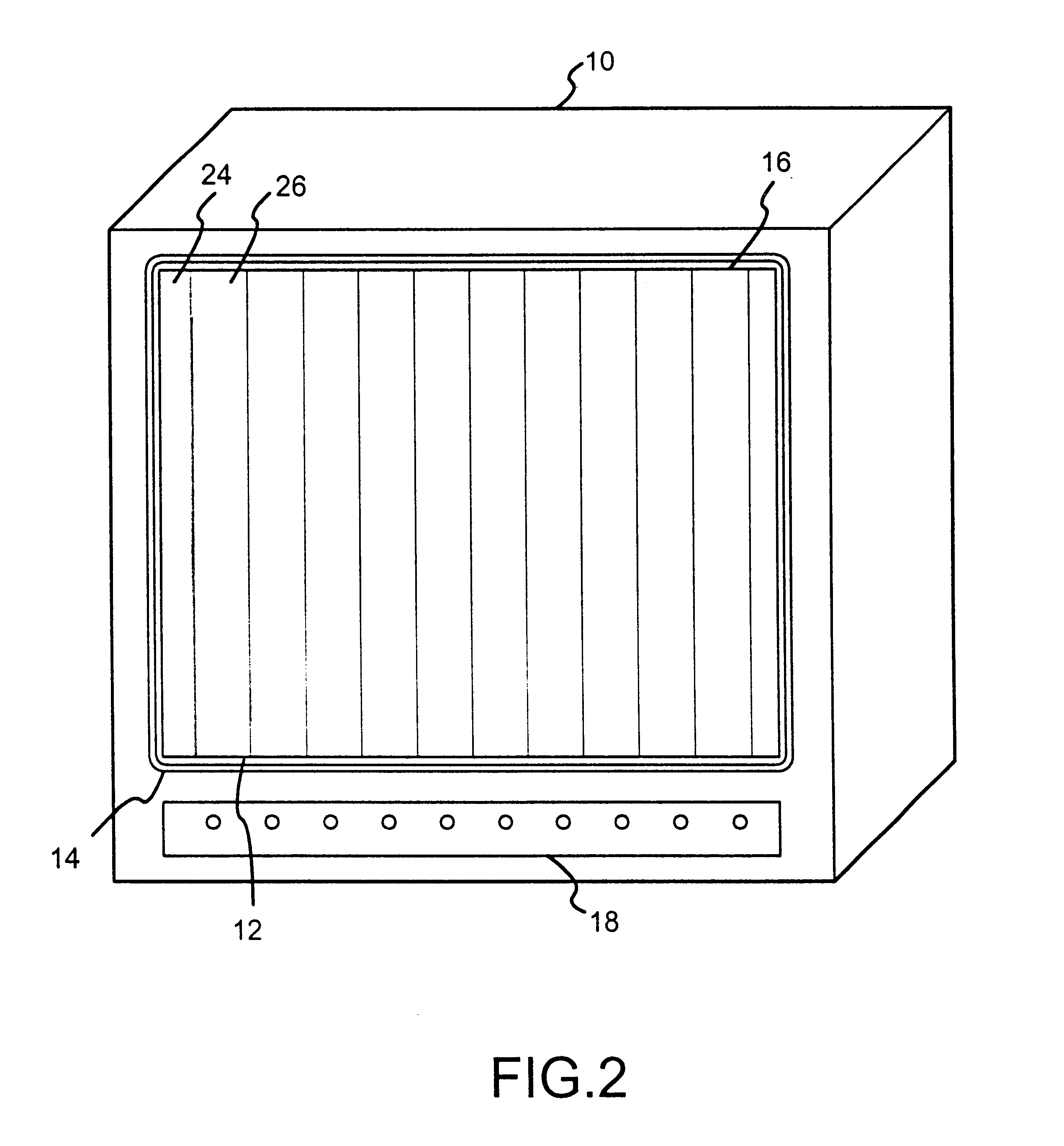
FIG. 2 is another schematic illustration of the display device 10 having a screen 12, a bezel 14, a vid...


PUM


Abstract

Disclosed is a high-speed approximation device that generates zone correction values in both the horizontal and vertical directions. Group correction values are stored for specific physical locations on the screen for each correction factor parameter. Higher resolution correction signals can be produced by generating zone correction values. Zone correction values are produced for binary fractional addresses that correspond to specific physical locations on the screen. By addressing specific binary fractional addresses that correspond to the location of the video image on the screen, new group correction values do not have to be produced each time the horizontal or vertical size or centering or frequency of the video image is changed. Additionally, by using start addresses and end addresses, zone correction values only have to be produced for the area which the video image occupies on the screen. The present invention also uses a high-speed binary fractional multiplier that multiplies a correction value by a series of binary numbers that simply shift the decimal location of the correction value to produce quotient values. Selection of the quotient values is made by a binary fractional address signal that indicates the specific address for the zone correction value to be generated. By transforming from an arbitrary line count address space to a binary physical address space, the present invention allows for the use of a simple and fast parallel binary fractional multiplier engine.

Description

A. Field of InventionThe present invention pertains generally to correcting the alignment of display devices and more particularly to digital zone control for correction and alignment of multimode display devices. This is achieved by determining the mapping of correction values for physical locations on a screen display using a high speed manner of generating incremental correction values between the physically located correction values and mapping the incremental correction values to scan lines using an approximation technique.B. Definitions"Address Quotient Value" means the physical division number divided by the number of scan lines of an image, for vertical geometry corrections, or by the number of pixels in a scan line, for horizontal geometry corrections."Physical Division Number" means the total number of physical divisions over that portion of the screen on which an image appears or that portion for which an image alignment is desired."Binary Order of Magnitude Number" means...

Claims


Application Information

Patent Timeline
IPC IPC(8): H04N17/04H04N3/233H04N3/22G09G1/00
CPCH04N17/04H04N3/2335G09G1/00
Inventor WEBB, JAMES R.SIMPSON, RON C.
Owner DISPLAY LAB
Learn More