Rotor

a rotor and rotational technology, applied in the field of rotors, can solve the problems of limited length of motor rotors, difficult production of permanent magnets, increased length of armor rings, etc., and achieves the effects of increasing the length of rotors, facilitating the manufacturing of permanent magnets, and increasing the division number of permanent magnets

Active Publication Date: 2021-02-02
TOYOTA JIDOSHA KK
View PDF8 Cites 0 Cited by
  • Summary
  • Abstract
  • Description
  • Claims
  • Application Information

AI Technical Summary

Benefits of technology

[0009]The present disclosure provides a rotor that is long along the axial direction of the rotary shaft without increasing the ratio L / D between the length L and the inner diameter D of the permanent magnet.
[0011]According to this aspect, the permanent magnet includes a plurality of sub-magnets that is divided in the axial direction of the rotary shaft. Such a plurality of sub-magnets along the axial direction of the rotary shaft increases the length of the rotor without increasing the ratio L / D between the length L and the inner diameter D of the sub-magnets by increasing division number of the permanent magnet. This facilitates the manufacturing of the permanent magnet, and the rotor has a length required to increase the output from the rotor and accordingly the output from the electric motor increases. This can fulfill the request for a high-pressure ratio and a high flow rate of a compressor in an electric supercharger, for example.
[0012]The connector intervenes between the two sub-magnets that are disposed adjacent to each other in the axial direction of the rotary shaft so that each protrusion of the sub-magnet fits to the corresponding recess of the connector or so that each recess of the sub-magnet fits to the corresponding protrusion of the connector. This enables positioning to specify the positional relationship around the axis of the rotary shaft between the two adjacent sub-magnets via the connector in the axial direction of the rotary shaft, and directs the easy-direction of magnetization of these two sub-magnets in the same direction.
[0014]Due to this configuration, the protrusion of the sub-magnet is firstly allowed to fit to the corresponding recess of the connector or the protrusion of the connector is firstly allowed to fit to the corresponding recess of the sub-magnet to connect the two sub-magnets to be adjacent in the axial direction of the rotary shaft via the connector. Next, while mutually fitting the connector and the sub-magnets, ends of two adjacent sub-rings along the axial direction of the rotary shaft are connected on the outer periphery of the connector, so as to define the connecting part of the ends of the two sub-rings on the outer periphery of the connector. This facilitates the manufacturing of the rotor.

Problems solved by technology

The conventional motor rotor as stated above, however, has a problem that an increase in length along the rotary shaft means an increase in the length of the armor ring and an increase in the ratio L / D between the length L and the inner diameter D of the permanent magnet, and such a permanent magnet is hard to produce.
The length of the motor rotor is therefore limited, and it is hard for the electric motor to increase the output.

Method used


Image

  • Rotor
  • Rotor
  • Rotor

Examples


Embodiment Construction

[0019]The following describes a rotor according to one embodiment of the present disclosure, with reference to the drawings.

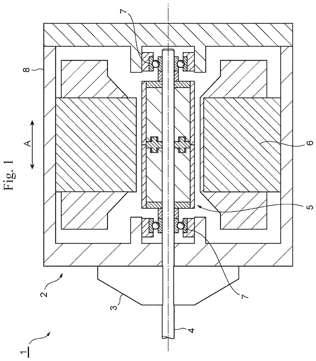
[0020]FIG. 1 is a schematic cross-sectional view of an air compressor 1 including a rotor 5 according to the present embodiment. The air compressor 1 includes an electric motor 2 and an impeller 3. The electric motor 2 includes a rotary shaft 4, a rotor 5, a stator 6, a bearing 7 and a casing 8. The impeller 3 is disposed at an end of the rotary shaft 4 that protrudes to the outside of the casing 8. Rotation of the impeller 3 with the rotary shaft 4 increases the air pressure. The air compressor 1 may be a part of an electric supercharger as described in JP 2010-200456 A as stated above.

[0021]The rotary shaft 4 has an impeller 3-side end and the other end on the other side of the impeller 3 that are rotatably supported by a pair of bearings 7 within the casing 8. In one example, the rotor 5 is fixed to the outer periphery of the rotary shaft 4 between the pair ...


PUM


Abstract

Provided is a rotor that is long in the axial direction of the rotary shaft without increasing the ratio L / D between the length L and the inner diameter D of the permanent magnet. The permanent magnet of the rotor includes a plurality of sub-magnets that are divided in the axial direction A of the rotary shaft. The armor ring includes a plurality of sub-rings that are divided in the axial direction A. The connector is disposed on the inner periphery of a connecting part between the two sub-rings and that are adjacent in the axial direction A and is disposed between the two sub-magnets that are adjacent in the axial direction A. The sub-magnets each have a recess that is depressed in the axial direction A. The connector has protrusions that fit to the recesses of the magnet.

Description

CROSS REFERENCE TO RELATED APPLICATIONS[0001]The present application claims priority from Japanese patent application JP 2018-093892 filed on May 15, 2018, the content of which is hereby incorporated by reference into this application.BACKGROUNDTechnical Field[0002]The present disclosure relates to a rotor for an air compressor or an electric motor.Background Art[0003]Conventionally inventions about a motor rotor suitable for an electric motor to be assembled into an electric supercharger have been known (see JP 2010-200456 A). The motor rotor described in JP 2010-200456 A has the following feature. The motor rotor includes a sleeve, a permanent magnet, a first end ring, a second end ring and an armor ring.[0004]The sleeve has a first end face and a second end face that define both end faces in the axial direction, and has a cylindrical shape like a sleeve that surrounds a rotary shaft around the axis. The sleeve includes an oil slinger that axially extends from the first end face t...

Claims


Application Information

Patent Timeline
Patent Type & Authority Patents(United States)
IPC IPC(8): H02K1/28H02K1/27F02B39/10
CPCH02K1/2726H02K1/28F02B39/10H02K1/274H02K1/2733
Inventor SADAMITSU, TAKAHIRO
Owner TOYOTA JIDOSHA KK
Why Eureka
Try Eureka