
System and method for compressing and decompressing images

a compression and image technology, applied in the field of systems and methods for increasing the compression of data streams, can solve problems such as excessive computational resources, requiring maximum improvement, and ignoring any regularities and correlations

Inactive Publication Date: 2001-08-28
UNILOC 2017 LLC
View PDF5 Cites 24 Cited by
  • Summary
  • Abstract
  • Description
  • Claims
  • Application Information

AI Technical Summary

Benefits of technology

Additionally, the particular combination of alternatives chosen from those described above can be dictated by a tradeoff of the processing power available in a proposed system against with the degree of improved data stream compression sought. In particular, it will be apparent that, for various classes of images and particular compression methods, the parameters of the methods and system of this invention can be optimized by routine methods to give maximum improved data stream compression.
It should now be appreciated that the objects of the present invention are satisfied. While the present invention has been described in particular detail, it should also be appreciated that numerous modifications are possible and will be apparent to one of skill in the art. These modifications are intended to be within the spirit and scope of the invention as claimed.

Problems solved by technology

However, such methods ignore any regularities and correlations that may occur between pixels in different pixel blocks which are treated as independent by these methods.
This reported work suffers from one or more problems, such as not being directed to maximally improving image compression, ignoring or at best inadequately treating regularities that may exist at scales in an image greater than a pixel block, requiring excessive computational resources, and so forth.

Method used


Image

  • System and method for compressing and decompressing images
  • System and method for compressing and decompressing images
  • System and method for compressing and decompressing images

Examples


Embodiment Construction

In this section, the general method implemented in improved encoder / decoder systems according the present invention is described, followed by exemplary improved MPEG encode / decoder systems.

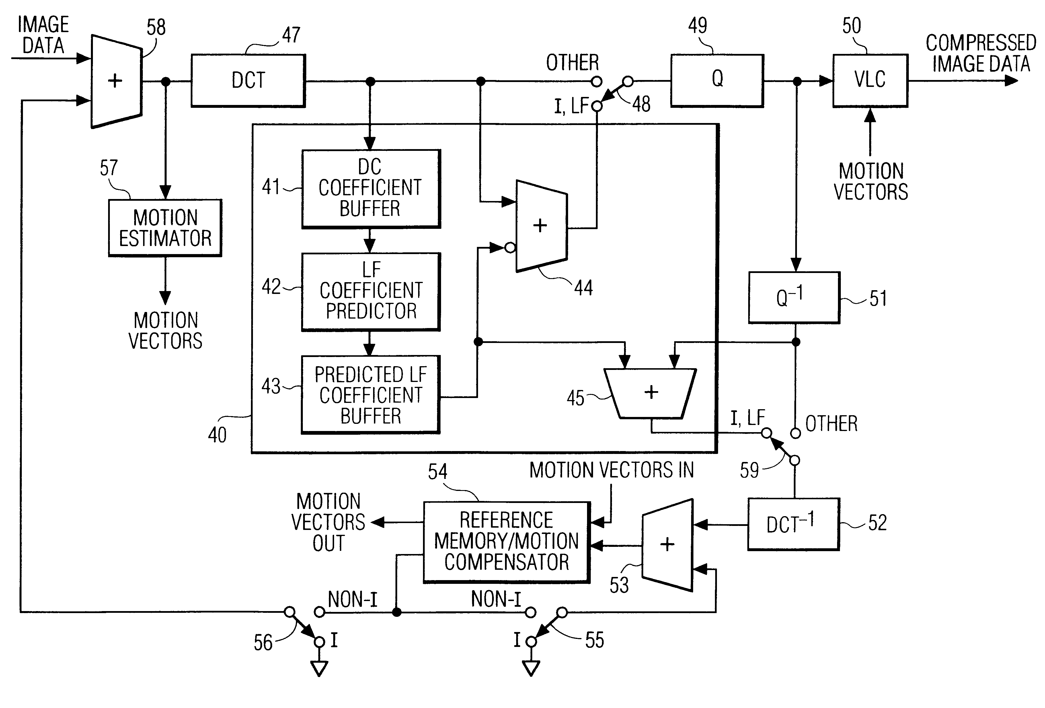
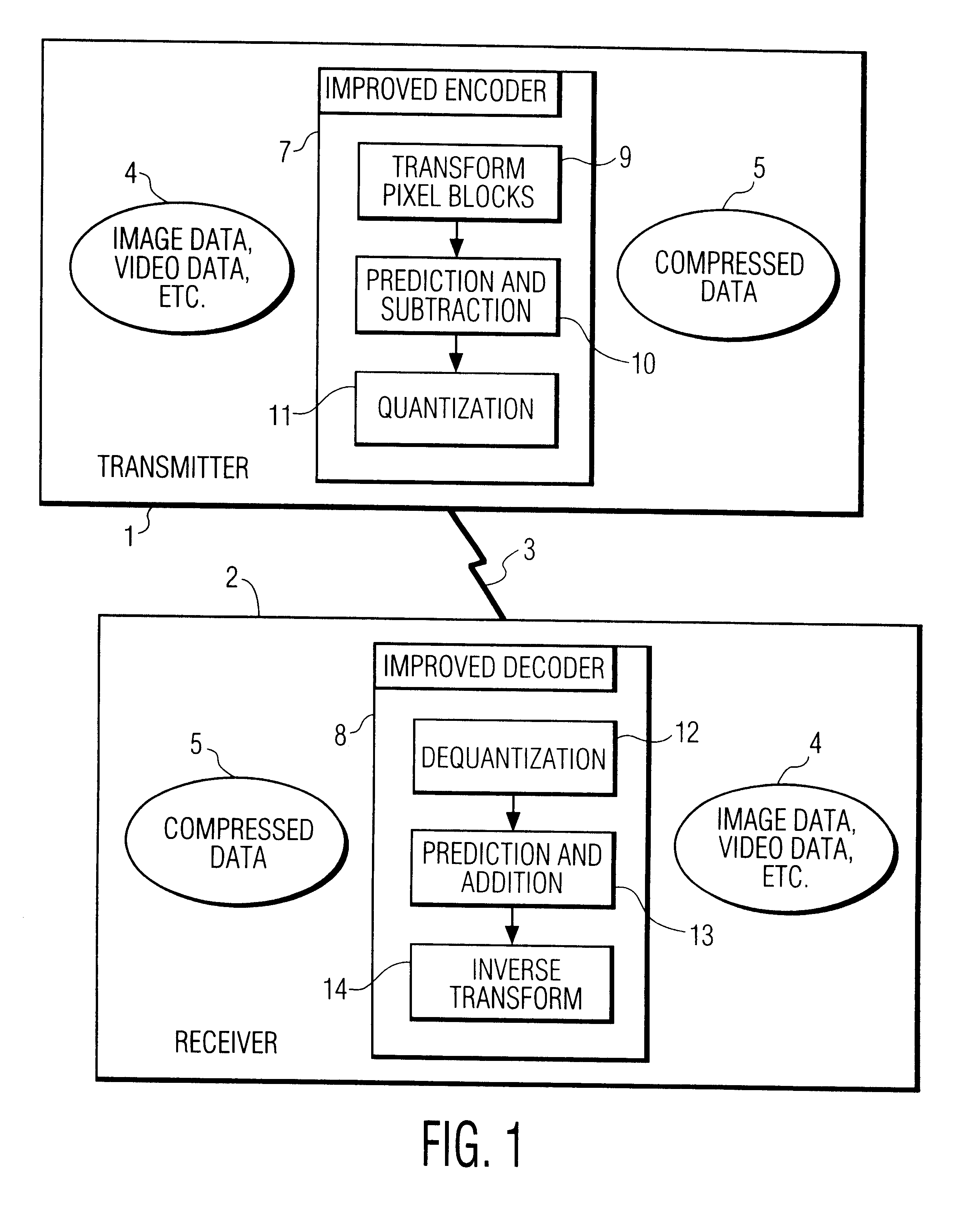
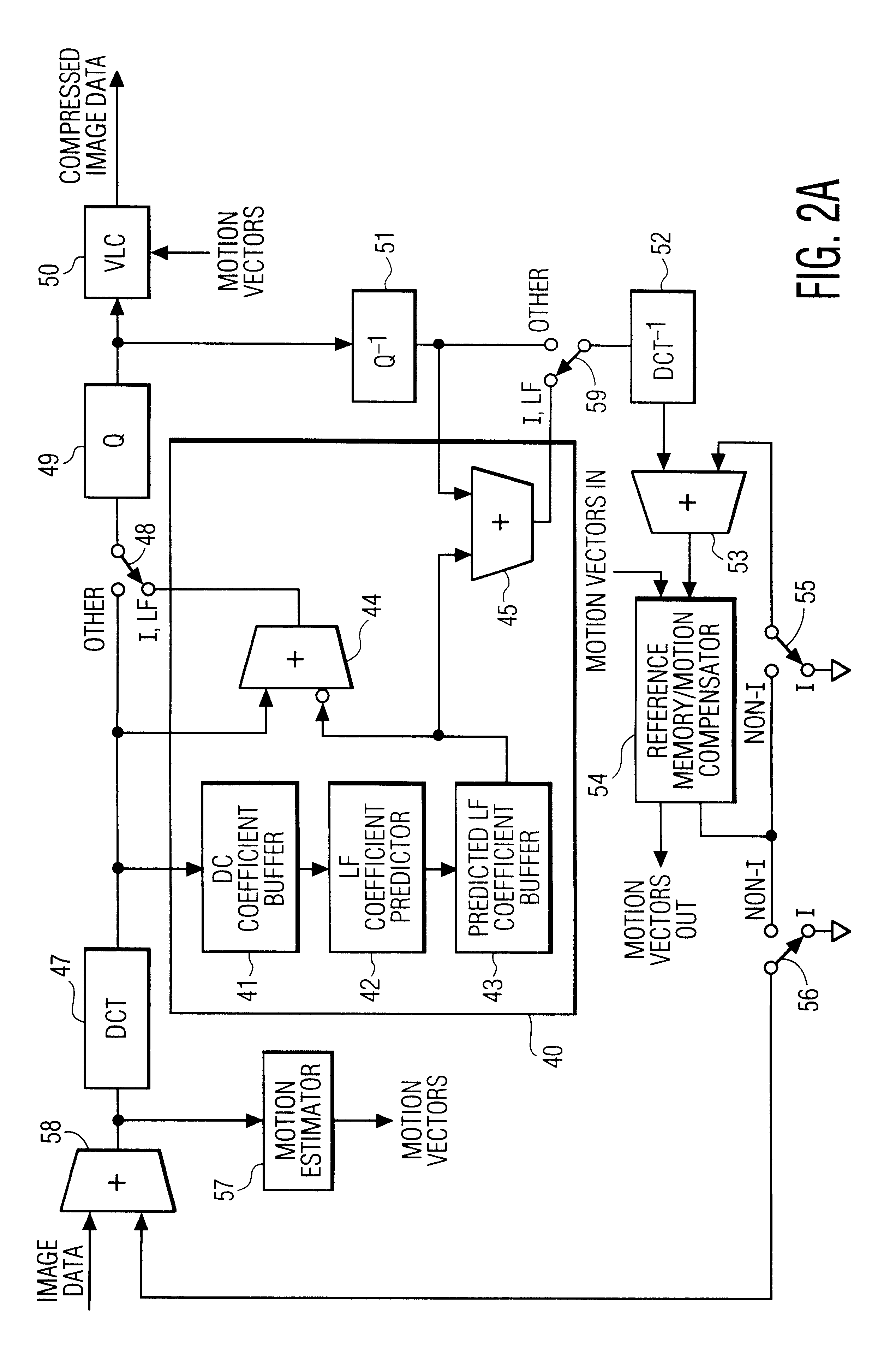
FIG. 3A illustrates the general method implemented in the systems of the present invention. According to FIG. 3A and as described above, non-overlapping sub-blocks dividing an image are first transformed to a transform, or frequency, domain, and the resulting transform coefficients are input 20 to the general method of this invention. Preferably, 8.times.8 pixel sub-blocks are transformed into the frequency domain by a DCT transform. For each sub-block, from its zero-frequency, or DC, transform coefficient, which is known to be proportional to the average pixel intensity in that sub-block, and from the DC coefficients of the adjacent sub-blocks, step 21 predicts selected low-frequency ("LF") transform coefficients of that block. Then, step 22 forms difference coefficients by subtracting the predic...


PUM


Abstract

This invention relates to systems and methods for increasing image compression. The systems and methods are improvements applicable to encoder / decoders which compress images by, inter alia, transforming non-overlapping independent blocks of pixels into a frequency domain and then quantizing the resulting frequency domain coefficients. The invention achieves increased compression by predicting low frequency coefficients of a block from, preferably, the average intensities, or zero frequency coefficients, of the block and its adjacent blocks. In an encoder, the low frequency coefficients are predicted, are then subtracted from the actual transform coefficients, and the difference coefficients are transmitted to a decoder. In the decoder, the low frequency coefficients are again predicted, are added to the received difference coefficients, and the resulting actual transform coefficients are used to reconstruct an image.

Description

1. Field of the InventionThe present invention relates to systems and methods for increasing compression of data streams containing image data, and in particular to systems and methods that increase compression by predicting values for certain low frequency coefficients of pixel block transforms.2. Description of the Related ArtMany important image compression methods process images as independent blocks of pixels. For example, such families of compression standards as JPEG, MPEG, H.320, and so forth, specify a step involving discrete cosine transformation ("DCT") of independent, non-overlapping 8.times.8 blocks of pixels in the source image followed by quantization of the resulting transform coefficients. See, e.g., Jack, 1996, Video Demystified, HighText Interactive Inc., San Diego, Calif. The quantized transform coefficients are transmitted from a transmitter-encoder to a receiver-decoder.Such transformation and quantization together achieve compression by exploiting the signific...

Claims


Application Information

Patent Timeline
IPC IPC(8): G06T9/00H04N7/34H04N7/50H04N7/32H03M7/30H03M7/36H03M7/40H04N1/41H04N19/593
CPCH04N19/105H04N19/18H04N19/593H04N19/61G06T9/00
Inventor RACKETT, ALBERT E.
Owner UNILOC 2017 LLC
Learn More