Thin-film transistor having a high resistance back channel region and fabrication method thereof

a technology of back channel region and thin film, which is applied in the direction of transistors, semiconductor devices, electrical equipment, etc., can solve the problems of n.sup.+-type amorphous silicon film 1105 having a high off-resistance of 10.sup.9 .omega or higher, and the inability to provide a good operational characteristic and reliability with a good fabrication yield

Inactive Publication Date: 2001-09-04
VISTA PEAK VENTURES LLC
View PDF15 Cites 41 Cited by
  • Summary
  • Abstract
  • Description
  • Claims
  • Application Information

AI Technical Summary

Problems solved by technology

However, there is a drawback that they cannot provide a good operational characteristic and reliability with a good fabrication yield, while they offer an advantage of increased simplicity.
Specifically, a first problem is that the off-characteristic of a thin-film transistor degrades and accordingly, the operational reliability is decreased with age or time.
A second problem is that the n.sup.+ -type amorphous silicon film 1105 having a high off-resistance of 10.sup.9 .OMEGA. or higher is very difficult to be realized in the first and second conventional transistors in FIGS. 1 and 2.
This is because the electric resistance of the film 1105 is very sensitive to the doping concentration of phosphorus from the phosphine gas and others and consequently, the formation process of the film 1105 is difficult to be controlled.
With the third conventional transistor shown in FIG. 3, the plasma doping process is difficult to be controlled.
This means that no good reproducibility is realized.
A fourth problem is that a process of forming the channel protection film 1209 or 1219 is necessary and as a result, the number of fabrication processes is increased in the fourth and fifth conventional transistors shown in FIGS. 4 and 5.
Thus, the leakage current cannot be thoroughly prevented in the fifth conventional transistor.
A fifth problem is that the fifth conventional transistor in FIG. 5, which has the improved characteristic as shown with the curve "c" in FIG. 8, increases the number of steps in the fabrication processes.
This is because the transistor is damaged by the ion implantation and thus, any repairing process is required for repairing the damage.

Method used


Image

  • Thin-film transistor having a high resistance back channel region and fabrication method thereof
  • Thin-film transistor having a high resistance back channel region and fabrication method thereof
  • Thin-film transistor having a high resistance back channel region and fabrication method thereof

Examples


first embodiment

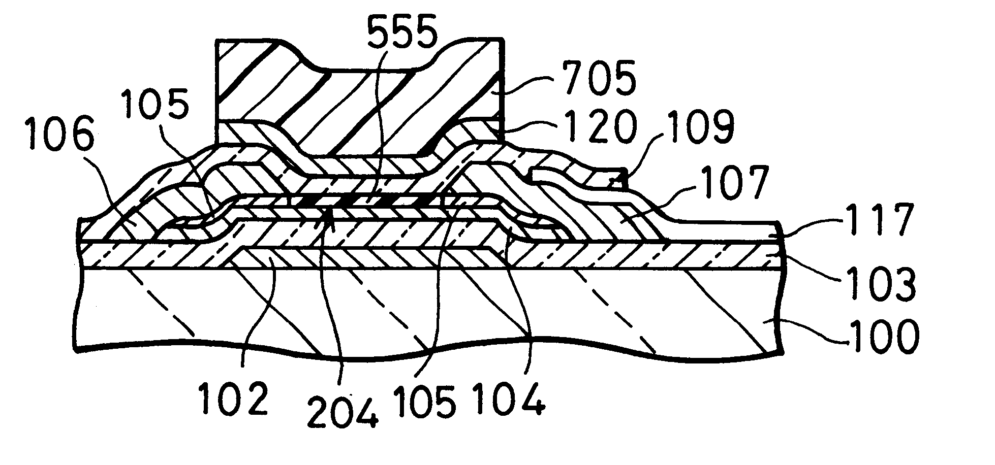
A thin-film transistor according to the invention is of an inverted staggered type, as shown in FIG. 9.

A gate electrode 102 is formed on a substrate 100 made of a quartz glass. The gate electrode 102 is formed by a patterned chromium (Cr) film (200 nm thick). A silicon nitride (SiN.sub.x) film (300 nm thick), which serves as a gate insulating film 103, is formed on the substrate 100 to cover the gate electrode 102.

An undoped, hydrogenated amorphous silicon (Si) film (30 nm thick) 104 is formed on the gate insulating film 103. An electrically conductive channel is formed in the film 104 under application of a suitable gate voltage. An n.sup.+ -type hydrogenated amorphous silicon film (5 nm thick) 105, which is doped with phosphorus, is formed on the film 104. The n.sup.+ -type hydrogenated amorphous silicon film 105 serves to form source and drain contact regions. The two hydrogenated amorphous silicon films 104 and 105 are patterned to be an island to be opposed to (or, be overlappe...

second embodiment

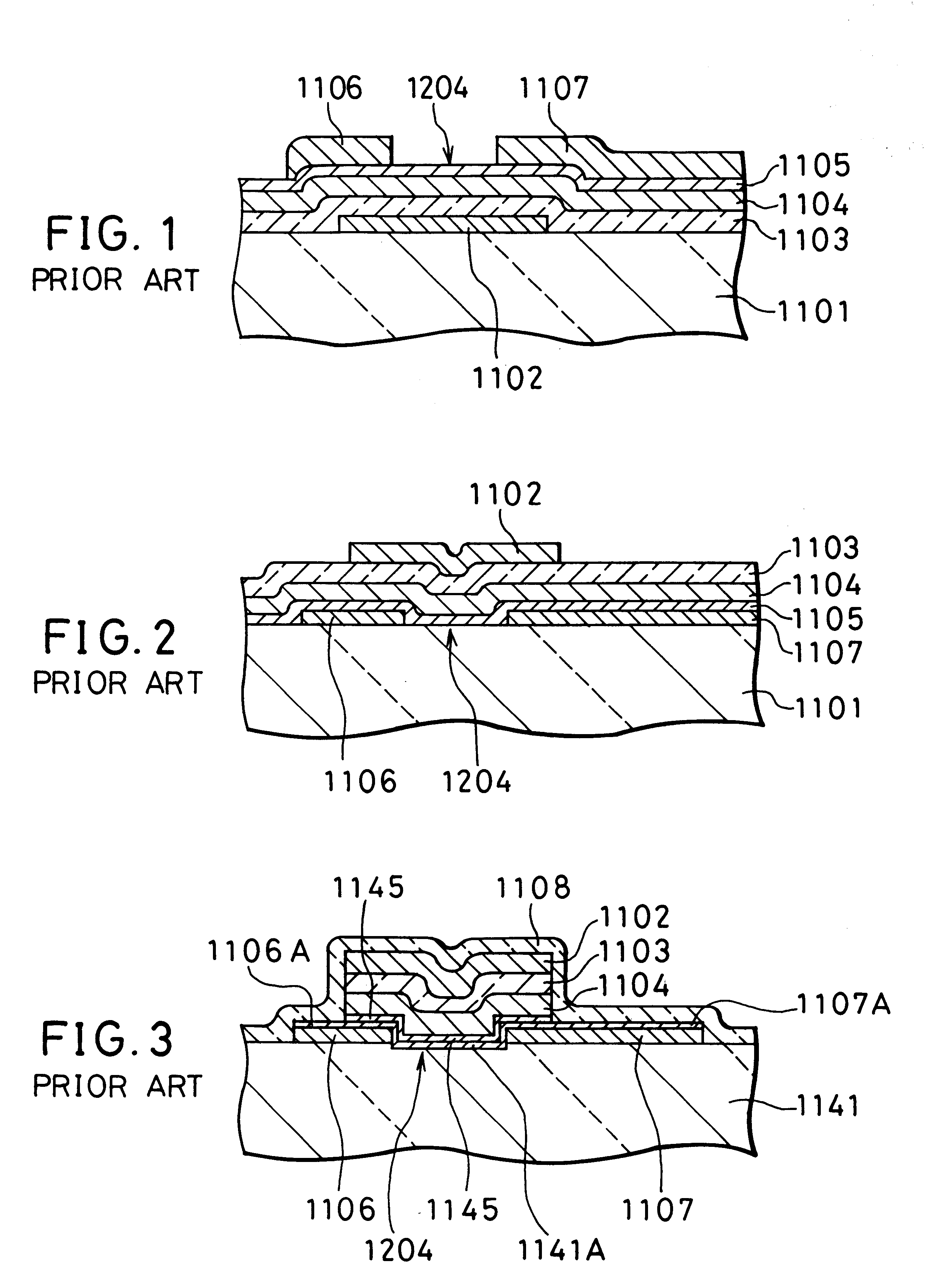
FIG. 11 shows a thin-film transistor according to a second embodiment, which is of a staggered type.

In FIG. 11, a silicon oxide (SiO.sub.x) film 229 (400 nm thick) is deposited on a substrate 100 made of a soda-lime glass. A silicon nitride (SiN.sub.x) film may be used instead of the silicon oxide film.

A source electrode 107, a drain electrode 106, and a pixel electrode 117 are formed on the silicon oxide film 229. The source electrode 107 is unified with the pixel electrode 117. The source, drain, and pixel electrodes 107, 106, and 117 are formed by patterning an ITO film (100 nm thick).

On the source electrode 107, the drain electrode 106, and the area between these electrodes 107 and 106, a non-doped hydrogenated amorphous silicon film 104 (20 nm thick), a gate insulating film 103 made of a silicon nitride (SiN.sub.x) film (200 nm thick), and a gate electrode 102 made of a molybdenum (Mo) film (250 nm thick) are formed to be stacked. The silicon film 104, the gate insulating film ...

third embodiment

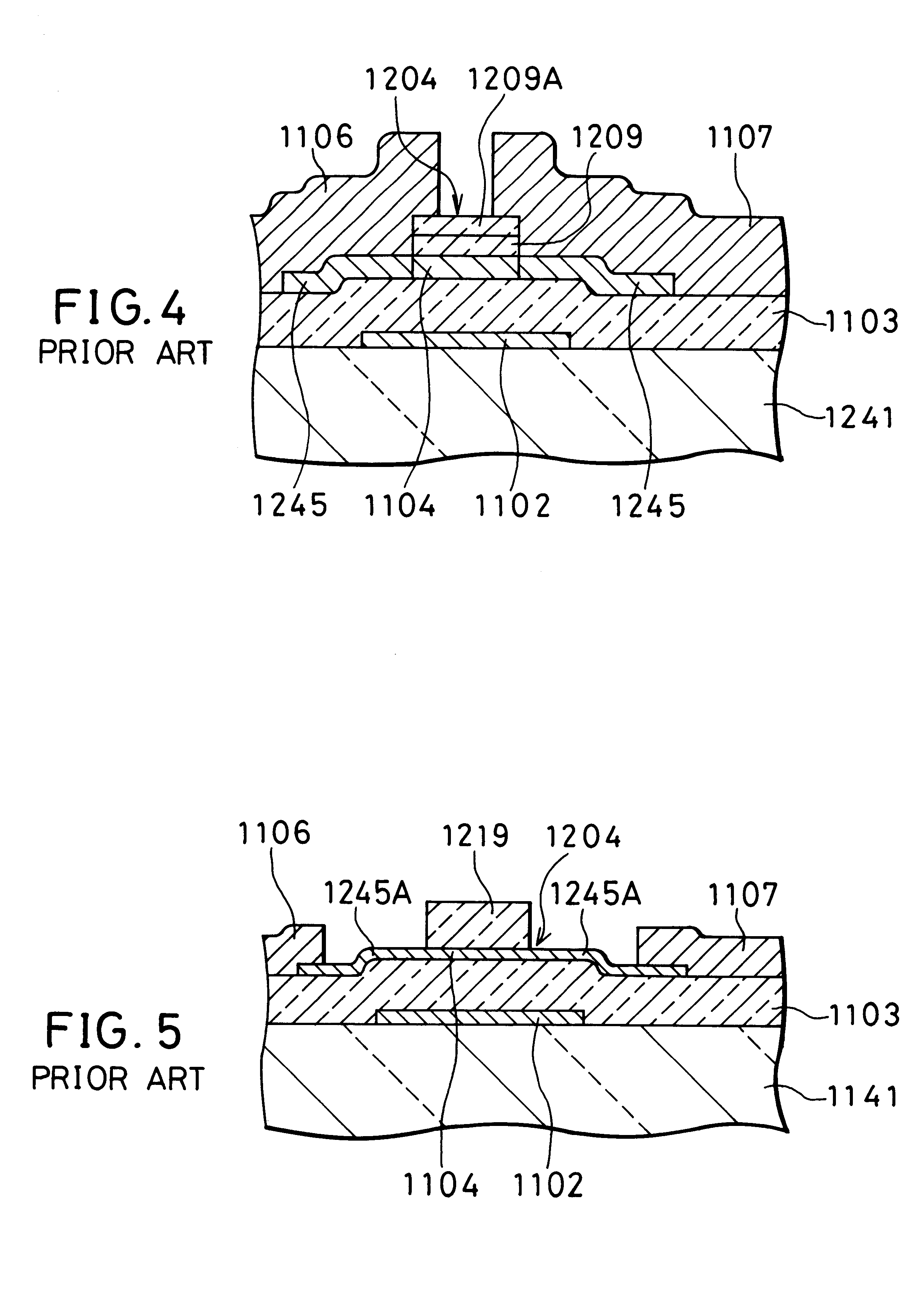
FIG. 13 shows a thin-film transistor of an inverted staggered type according to a third embodiment.

A gate electrode 102 is formed on a substrate 100 made of an aluminum silicate glass. The gate electrode 102 is formed by a patterned chromium (Cr) film (150 nm thick). A silicon nitride (SiN.sub.x) film (350 nm thick), which serves as a gate insulating film 103, is formed on the substrate 100 to cover the gate electrode 102.

An undoped, hydrogenated amorphous silicon (Si) film (70 nm thick) 104 is formed on the gate insulating film 103. An n.sup.+ -type hydrogenated amorphous silicon film (3 nm thick) 105, which is doped with phosphorus, is formed on the film 104. The n.sup.+ -type hydrogenated amorphous silicon film 105 serves to form source and drain contact regions. The two hydrogenated amorphous silicon films 104 and 105 are patterned to be an island to be opposed to (or, be overlapped with) the gate electrode 102.

A source electrode 107 and a drain electrode 106 are formed on the e...


PUM


Abstract

A thin-film transistor is provided, which has a simple configuration and improved off-characteristic, operational reliability, and fabrication yield. This transistor includes a substrate and a layered structure formed on the substrate. The layered structure includes a semiconductor film, a gate insulating film located on a first side of the semiconductor film to be overlapped with the semiconductor film, a gate electrode located on the gate insulating film on the first side of the semiconductor film to be selectively overlapped with the semiconductor film, a source electrode located on a second side of the semiconductor film to be electrically connected to the semiconductor film, and a drain electrode located on the second side of the semiconductor film to be electrically connected to the semiconductor film and to be apart from the source electrode. The semiconductor film has a back channel section between opposite ends of the source and drain regions. The back channel section includes a high-resistance part generated by doping n- and p-type impurities.

Description

1. Field of the InventionThe present invention relates to a thin-film transistor and a fabrication method thereof and more particularly, to a thin-film transistor that is capable of a highly reliable operation for use as a liquid crystal display (LCD) device and others and that is readily fabricated, and a fabrication method of the transistor.2. Description of the Prior ArtUnlike conventional monolithic transistors that are formed in the inside of a semiconductor substrate, thin-film transistors are fabricated by stacking several thin films on a substrate. Therefore, the thin-film transistors have a simple and easy-to-fabricate configuration compared with the monolithic transistors. As a result, the thin-film transistors have been in widespread use as, for example, switching elements in a large-sized electronic device such as an LCD device.Further, the simplicity of the device configuration and fabrication method of the thin-film transistors makes it possible to fabricate various ap...

Claims


Application Information

Patent Timeline
Patent Type & Authority Patents(United States)
IPC IPC(8): H01L29/66H01L21/336H01L21/02H01L29/786
CPCH01L29/66765H01L29/78669H01L29/78666H01L29/772
Inventor NOGUCHI, KESAO
Owner VISTA PEAK VENTURES LLC
Why Eureka
Try Eureka