Method and control system for compensating for friction

a control system and friction technology, applied in the direction of programme control, fluid pressure control, instruments, etc., can solve the problems of static friction, static friction may occur in other positions of the valve, and control occurs slowly, so as to reduce the effect of static friction

a control system and friction technology, applied in the direction of programme control, fluid pressure control, instruments, etc., can solve the problems of static friction, static friction may occur in other positions of the valve, and control occurs slowly, so as to reduce the effect of static friction

US6285913B1Inactive Publication Date: 2001-09-04ALFA LAVAL AUTOMATION

Image

  • Method and control system for compensating for friction
  • Method and control system for compensating for friction
  • Method and control system for compensating for friction

Examples


Embodiment Construction

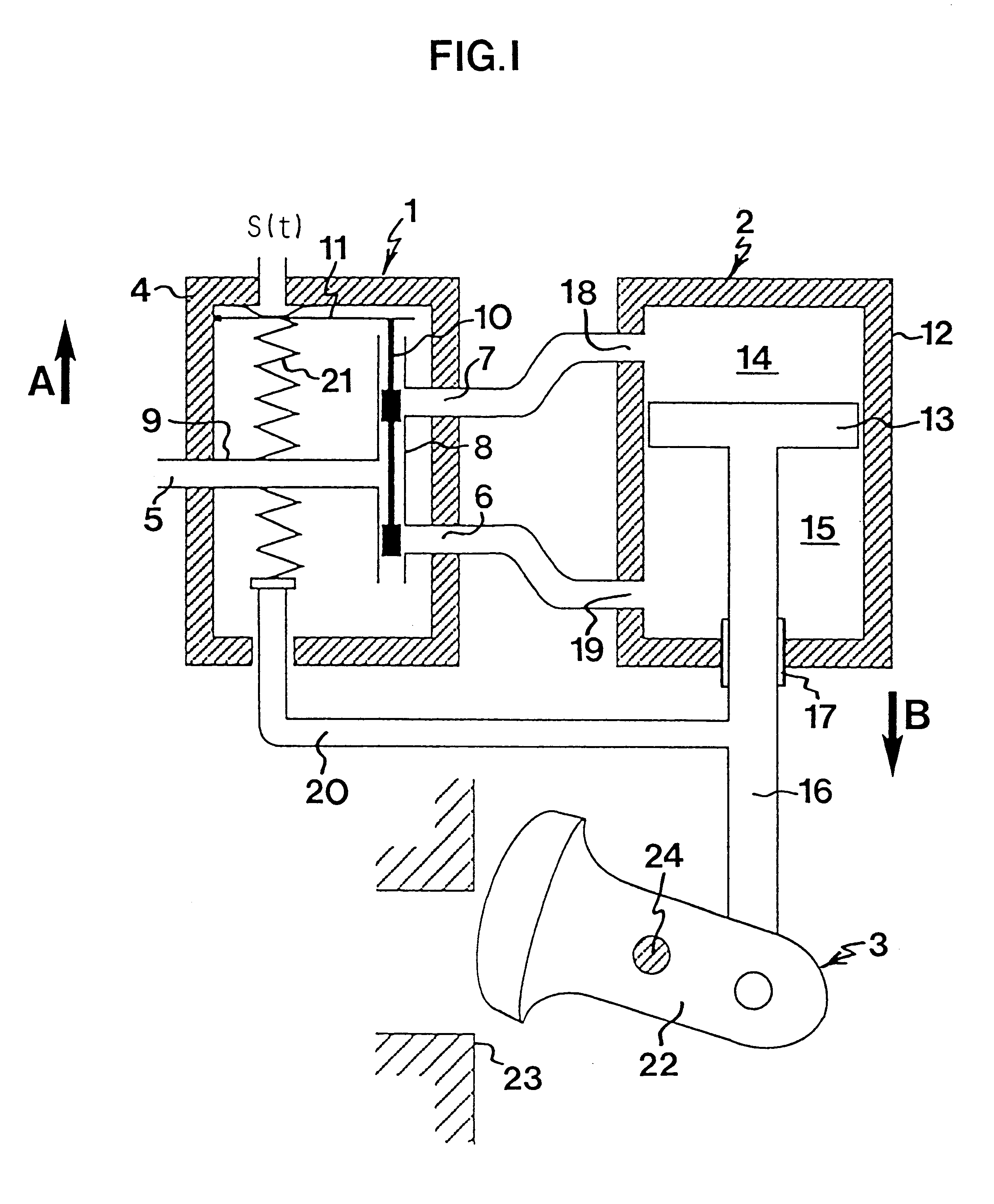
FIG. 1 is a schematic view of one type of pneumatic control valve. The three main parts of the control valve are a valve positioner 1, an actuator 2 and a valve 3, the actuator 2 and the valve 3 together forming an actuating means, i.e. the means subjected to the above-mentioned static friction.

The valve positioner 1 is arranged in a casing 4, which is provided with an air supply opening 5, a lower connecting port 6 and an upper connecting port 7. The air supply opening 5 is connected to a compressed air source (not shown) applying a constant air pressure to the valve positioner 1. The connecting ports 6, 7 are interconnected by means of a first duct 8, which in turn is connected to the air supply opening 5 by means of a second duct 9. In the first duct 8, a pilot valve 10 is arranged in the form of a movable slide, which is connected to an operable diaphragm 11.

The actuator 2 comprises a cylinder 12 and a piston 13 movably arranged in the cylinder and dividing the cylinder into an ...


PUM


Abstract

A method for compensating for static friction in an actuating device includes the steps of generating an actual signal y2(t) corresponding to a quantity which is controllable by the actuating device, generating a set value signal y1(t) generating a control signal s1(t) based on the set value signal y1(t) and the actual value signal y2(t), and supplying the control signal to the actuating device for controlling the same. The method also includes the steps of generating an intermittent signal s2(t) compensating for friction, sensing the sign of the derivative with respect to time of the control signal s1(t), giving the signal s2(t) compensating for friction the same sign as the derivative, and adding the signal s2(t) compensating for friction to the control signal s1(t) before supplying the same to the actuating device.

Description

The present invention relates to controlling in the presence of static friction, especially to reducing the effects of static friction in the controlling of valves.Static friction, so-called stiction, occurs everywhere in the environment. As a rule, the friction when passing from rest to motion (static friction) is greater than the friction during the continuance of the motion (sliding friction). To move an object from its resting position, a force greater than the sliding friction must thus be applied to the object.The existence of static friction is a general problem in all types of controlling that means that an actuating means is to be stopped and later to be moved again. The term actuating means signifies in this context the subject of the control, i.e. the component / components actuated during the control.In valves there is static friction, for instance, between the valve spindle and the packing box, especially if this is tightened firmly. Moreover, static friction may occur in...

Claims


Application Information

Patent Timeline
04 Sep 2001
Publication
US6285913B1
IPC
G05D16/02; G05D16/00
CPC
G05D16/02; F15B9/09; F15B9/12; F15B13/044; F15B2211/326; F15B2211/327; F15B2211/328; F15B2211/86
Inventors
HAGGLUND, TORE