

Apparatus and method for high temperature viscosity and temperature measurements
a technology of viscosity and apparatus, applied in the direction of instruments, heat measurement, specific gravity measurement, etc., can solve the problems of no sensors currently available for on-line (in-situ) viscosity measurement, no sensors currently available which simultaneously, and significant errors in viscosity measuremen
Inactive Publication Date: 2001-10-02
MISSISSIPPI STATE UNIVERSITY
View PDF12 Cites 38 Cited by
- Summary
- Abstract
- Description
- Claims
- Application Information
AI Technical Summary
Problems solved by technology
Any slight change in composition, and / or errors in temperature measurement leads to significant errors in viscosity measurement.
There are no sensors currently available for measurement of the on-line (in-situ) viscosity measurement for melts at very high temperatures (above 1000.degree. C.).
There are no sensors currently available which simultaneously measure temperature and viscosity.
Current methods for measuring temperatures using immersed thermocouples are not desirable due to frequent breakage and inconsistent readings.
This leads to a significant heat loss and cooling of molten metal at the probe / melt interface, or in other words, development of a "heat sink."
Online methods for measuring viscosity under these conditions are not currently available.
This leads to a significant heat loss associated with thermally conductive probes inserted in molten materials at very high temperatures, such as high temperature thermocouples.
This not only results in a reduced yield, but can result in eddies and disturbances in the molten flow, reducing quality.
Method used
View moreImage
Smart ImageViewing Examples

Examples
example 3
Using the buffer rod of Example 2, the viscosity of a melt prepared from a glass sample obtained from Ferro Corporation of MI, USA was measured. Viscosity was recorded real time and graphed against temperature measured at the same time. The result is reflected in FIG. 10.
example 4
Using the buffer rod of Example 2, temperature of a melt during heating and cooling as a glass melt was obtained, and compared with results obtained using an RTD thermocouple. The data is reflected in FIG. 9.
Login to View More PUM
| Property | Measurement | Unit |
|---|---|---|
| viscosities | aaaaa | aaaaa |
| temperatures | aaaaa | aaaaa |
| temperatures | aaaaa | aaaaa |
Abstract
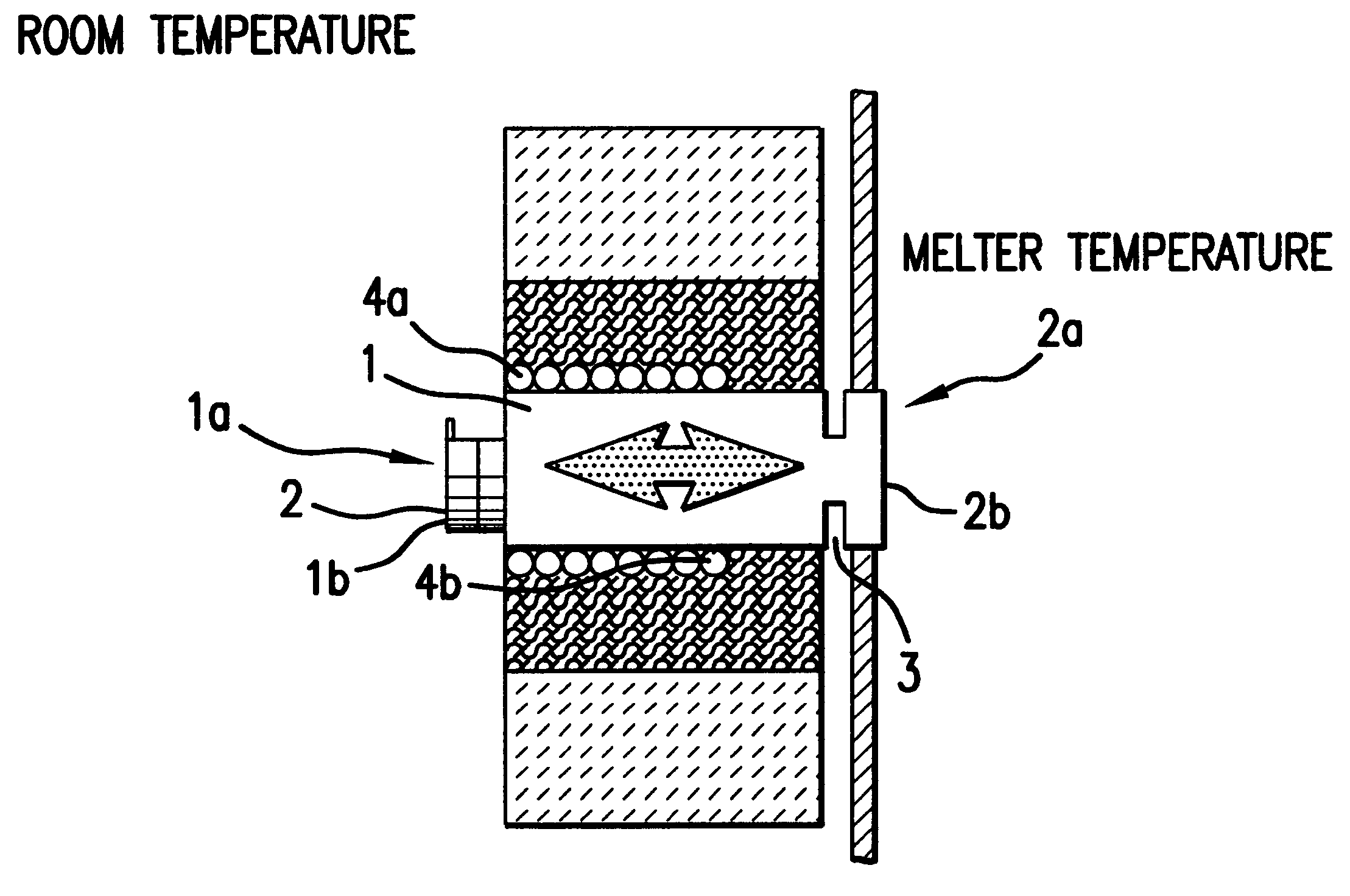
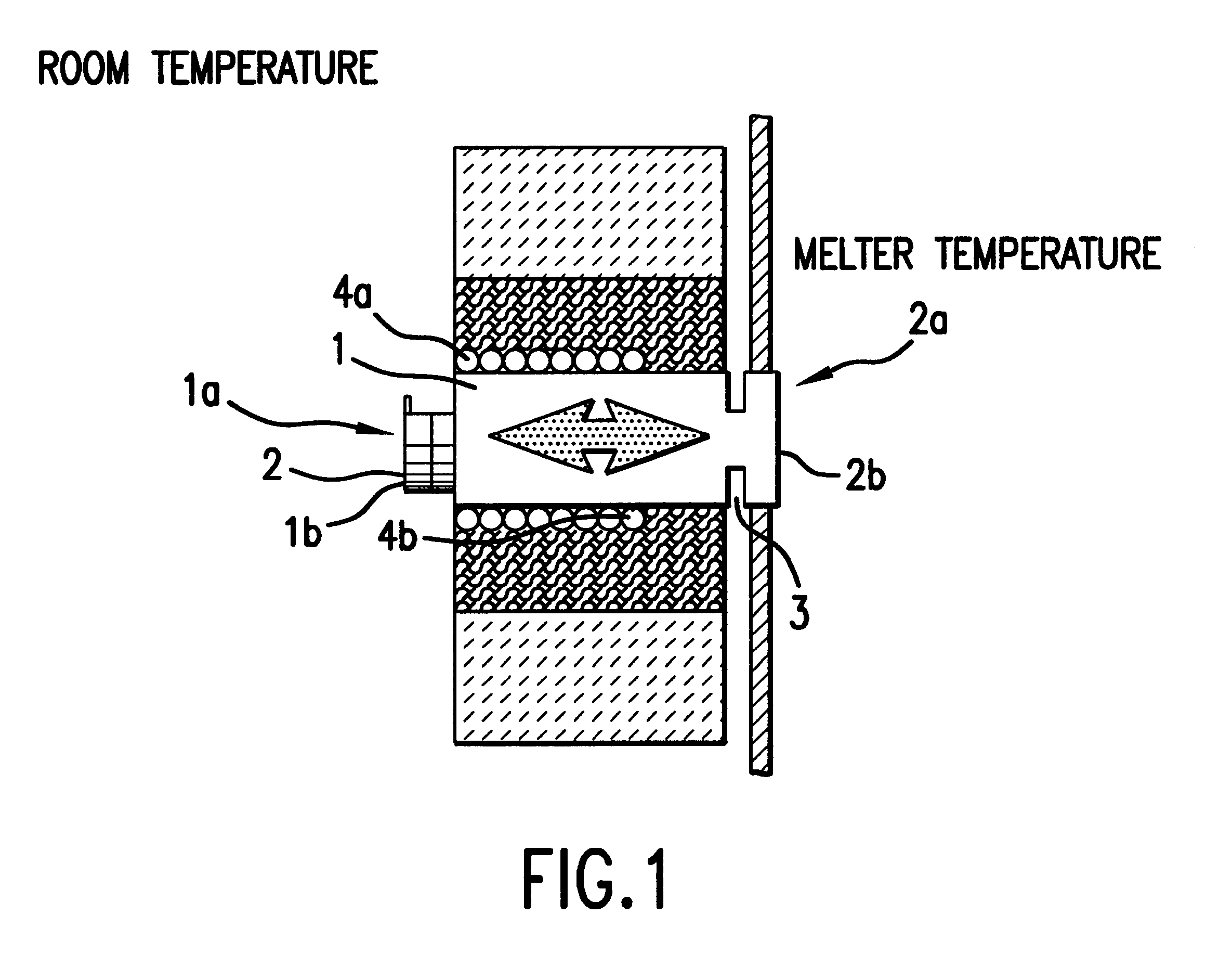
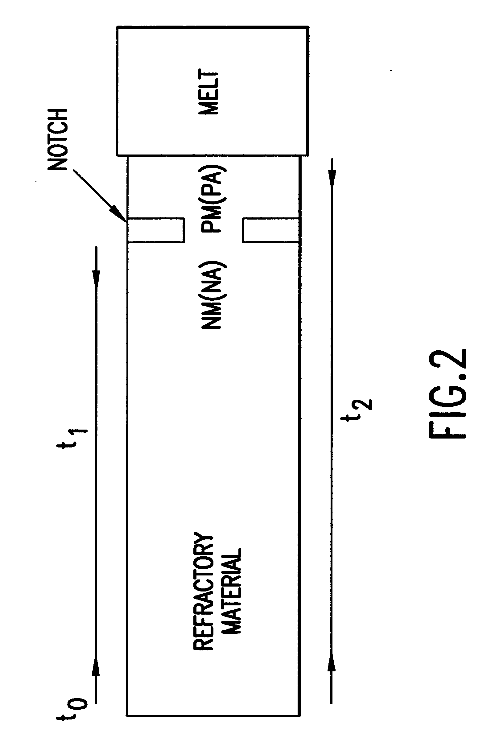
A probe for measuring the viscosity and / or temperature of high temperature liquids, such as molten metals, glass and similar materials comprises a rod which is an acoustical waveguide through which a transducer emits an ultrasonic signal through one end of the probe, and which is reflected from (a) a notch or slit or an interface between two materials of the probe and (b) from the other end of the probe which is in contact with the hot liquid or hot melt, and is detected by the same transducer at the signal emission end. To avoid the harmful effects of introducing a thermally conductive heat sink into the melt, the probe is made of relatively thermally insulative (non-heat-conductive) refractory material. The time between signal emission and reflection, and the amplitude of reflections, are compared against calibration curves to obtain temperature and viscosity values.
Description
1. Field of the InventionThe present invention relates to a method for the non-invasive and simultaneous measurement of viscosity and temperature in very hot liquids (melts) such as polymers, metals, and glass at temperatures ranging from 200.degree. C.-3000.degree. C.2. Discussion of the BackgroundMethods for measuring viscosity in liquids are known. Current methods employed for process control, at very high temperatures, infer viscosity from a temperature measurement. This assumes a predetermined relationship between viscosity and temperature. Any slight change in composition, and / or errors in temperature measurement leads to significant errors in viscosity measurement. There are no sensors currently available for measurement of the on-line (in-situ) viscosity measurement for melts at very high temperatures (above 1000.degree. C.). There are no sensors currently available which simultaneously measure temperature and viscosity. However, temperature measurement at high temperature i...
Claims
Login to View More Application Information
Patent Timeline
 Patent Type & AuthorityPatents(United States)
IPC IPC(8): G01N29/02G01N29/22G01N11/10G01N29/24G01N29/024G01N11/16G01K11/00G01K11/22G01N33/20
CPCG01K11/22G01N11/16G01N29/024G01N29/22G01N29/228G01N29/2462G01N33/206G01N2291/015G01N2291/0252G01N2291/02818G01N2291/02881G01N2291/0422G01N33/205
InventorBALASUBRAMANIAM, KRISHNANSHAH, VIMALCOSTLEY, R. DANIELSINGH, JAGDISH P.
OwnerMISSISSIPPI STATE UNIVERSITY