Circuit and method for switching between digital signals that have different signal rates

a digital signal and signal rate technology, applied in the direction of generating/distributing signals, pulse techniques, instruments, etc., can solve the problems of generating data errors, conventional approaches that do not operate properly, and different signal rates, so as to prevent glitches during switching operations, substantially different signal rates, and convenient implementation

Inactive Publication Date: 2001-10-02
SEIKO EPSON CORP
View PDF16 Cites 39 Cited by
  • Summary
  • Abstract
  • Description
  • Claims
  • Application Information

AI Technical Summary

Benefits of technology

An improved circuit and an improved method are disclosed that support switching operations between digital signals that may have substantially different signal rates. The improved circuit and method are particularly well suited for switching a bus between sources of data or strobe signals and sources of arbitration signals in conformance with IEEE Standard 1394. The improved circuit can be implement...

Problems solved by technology

Where signals having substantially different signal rates utilize the same signal path, various problems may arise due to the difference in signal rates.
If the maximum difference in signal rates between the signal sources exceeds about 100 MHz, this conventional approach does not operate properly.
The glitch may be interpreted as being part of a data signal, and consequently may generate data errors.
A glitch occurring when the multiplexor switches an arbitration signal onto the bus may be interpreted as being part of the arbitration signal, and could cause a receiving de...

Method used


Image

  • Circuit and method for switching between digital signals that have different signal rates
  • Circuit and method for switching between digital signals that have different signal rates
  • Circuit and method for switching between digital signals that have different signal rates

Examples


Embodiment Construction

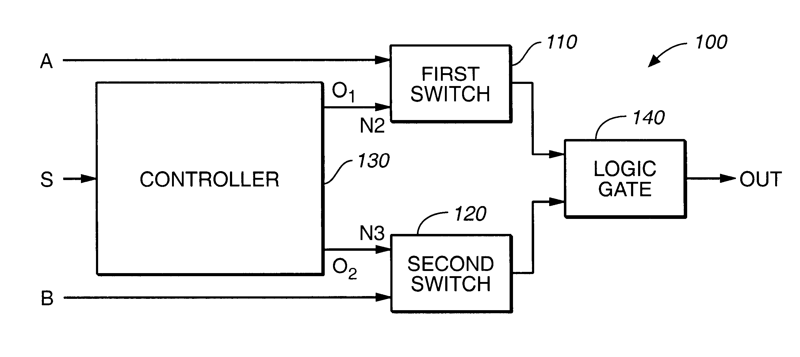
Disclosed are various embodiments of a circuit and a method for encoding a digital signal. Bits of the digital signal are beneficially encoded in parallel to reduce latency of encoding operations. Also disclosed are various embodiments of a circuit and a method for switching a signal that has a high signal rate onto the same signal path with another signal that has a low signal rate without producing a glitch on the signal path. Glitches are prevented even where the various signals have signal rates that differ by 50 MHz or more. The various circuits and methods are highly beneficial for encoding data signals to generate strobe signals, and for supplying such signals to the same signal path with an arbitration signal, in conformance with IEEE Standard 1394 of the Institute of Electrical and Electronics Engineers. The entirety of IEEE Standard 1394 is incorporated herein by reference.

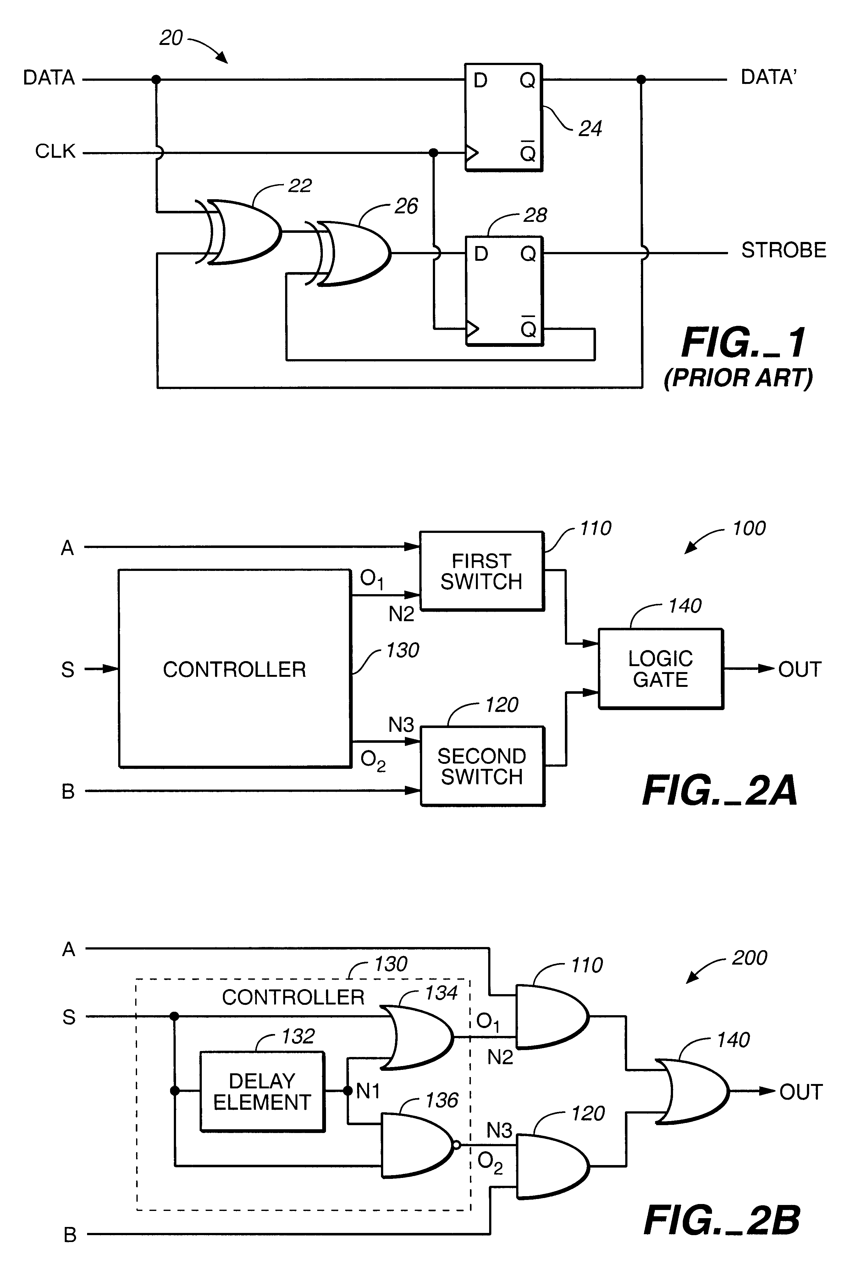
Referring now to FIG. 1, there is shown a schematic diagram of a conventional encoder 20 specified in...


PUM


Abstract

A circuit for switching digital signals on a plurality of signal lines where signals on different signals line may have different signal rates includes a controller that prevents a switch from being turned off until after another switch is stably turned ON. This allows more than one switch at a time to supply a correspondingly received digital signal to an output. Substantially identical digital signals may be supplied to two inputs of such a circuit while the circuit is switched between the respective inputs. The circuit may be driven by an encoder that supplies encoded signals without recursion but that conforms to encoding conventionally supplied by recursion. The encoder may be implemented in parallel configuration for rapid encoding of a signal, and may be implanted to perform a data strobe signal encoding conforming to IEEE standard 1394.

Description

The present invention is related to a circuit and a method for generating and switching between digital signals having different signal rates. More particularly, the present invention is related to encoding digital signals that have high signal rates to generate encoded signals, and further to switching such signals onto the same signal line with an arbitration signal having a low signal rate.In modern electronics, it is common for an integrated circuit to generate a variety of signal types. An integrated circuit may, for example, generate data signals that convey information at a high signal rate, and may also generate arbitration signals that have a substantially lower signal rate and are useful for controlling other devices. Where signals having substantially different signal rates utilize the same signal path, various problems may arise due to the difference in signal rates. For example, a false or spurious signal commonly known as a glitch may occur in an output signal on the s...

Claims


Application Information

Patent Timeline
IPC IPC(8): G06F13/42
CPCG06F13/4239
Inventor UYEHARA, CLINTONCHIANG, KUANG-YU
Owner SEIKO EPSON CORP
Why Eureka
Try Eureka