Liquid crystal display apparatus

a technology of liquid crystal display and display screen, which is applied in the direction of instruments, non-linear optics, optics, etc., can solve the problems of increasing and achieve the effects of reducing the load on the manufacturing process correspondingly, suppressing the fluctuation of pixel-based gradation, and controlling more stably

Inactive Publication Date: 2001-10-09
VISTA PEAK VENTURES LLC
View PDF11 Cites 32 Cited by
  • Summary
  • Abstract
  • Description
  • Claims
  • Application Information

AI Technical Summary

Benefits of technology

Also preferably, the control electrode extending along the first opening has its ends elongated slightly so as to serve simultaneously as an interconnection for a control electrode provided in a neighboring other pixel electrode. Since a process of forming the interconnection can be omitted, it is possible to reduce the load on the manufacturing process correspondingly.
With the liquid crystal display devices according to the present ...

Problems solved by technology

Namely, the above-described orientation splitting type liquid crystal display device has a drawback that minute domains with different directions of orientation tend to be produced in each of the split regions. FIG. 9 shows a plan view of the defective orientation domains in the above-described conventional liquid crystal display device.
This liquid crystal display device has...

Method used


Image

  • Liquid crystal display apparatus
  • Liquid crystal display apparatus
  • Liquid crystal display apparatus

Examples


first embodiment

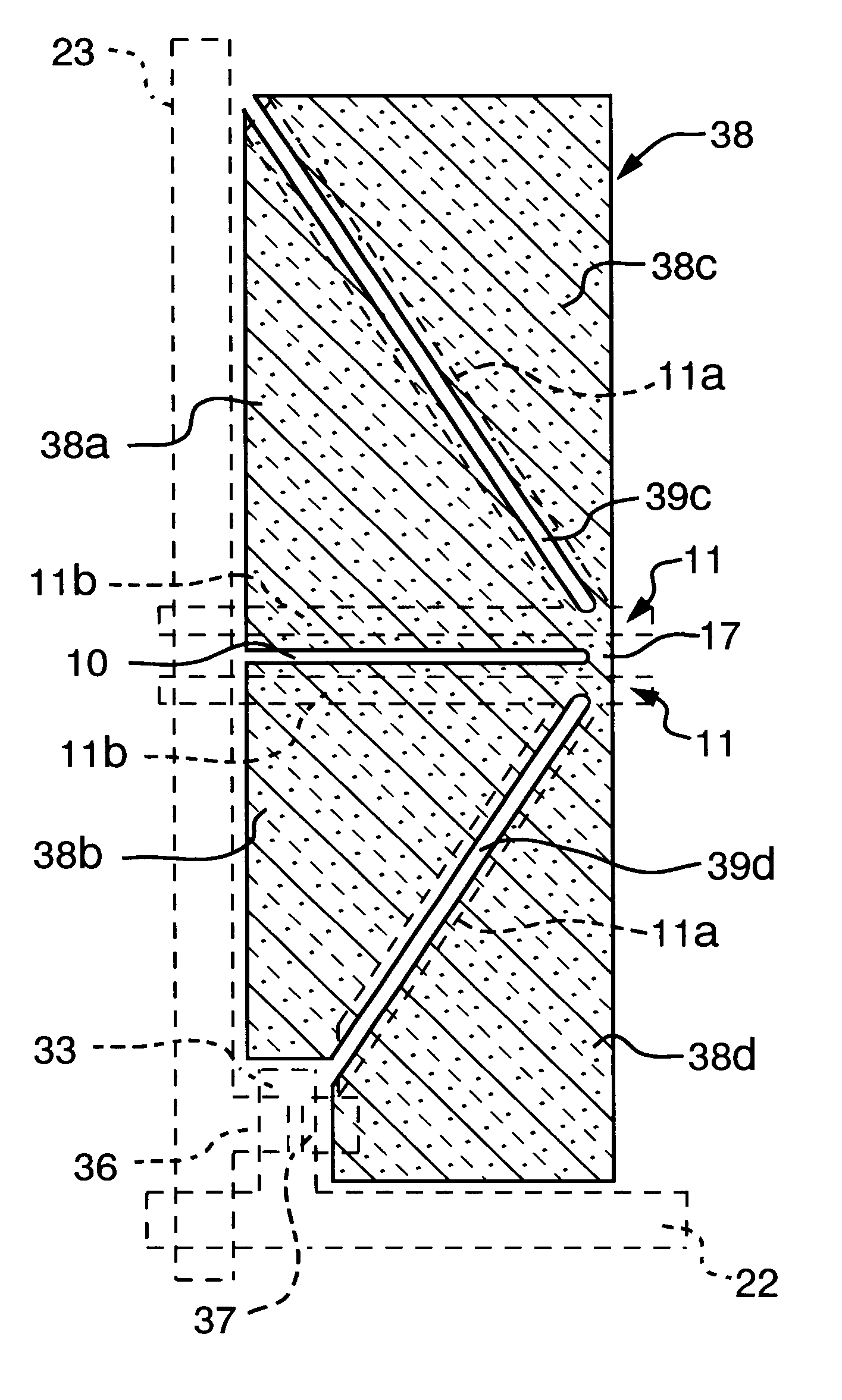
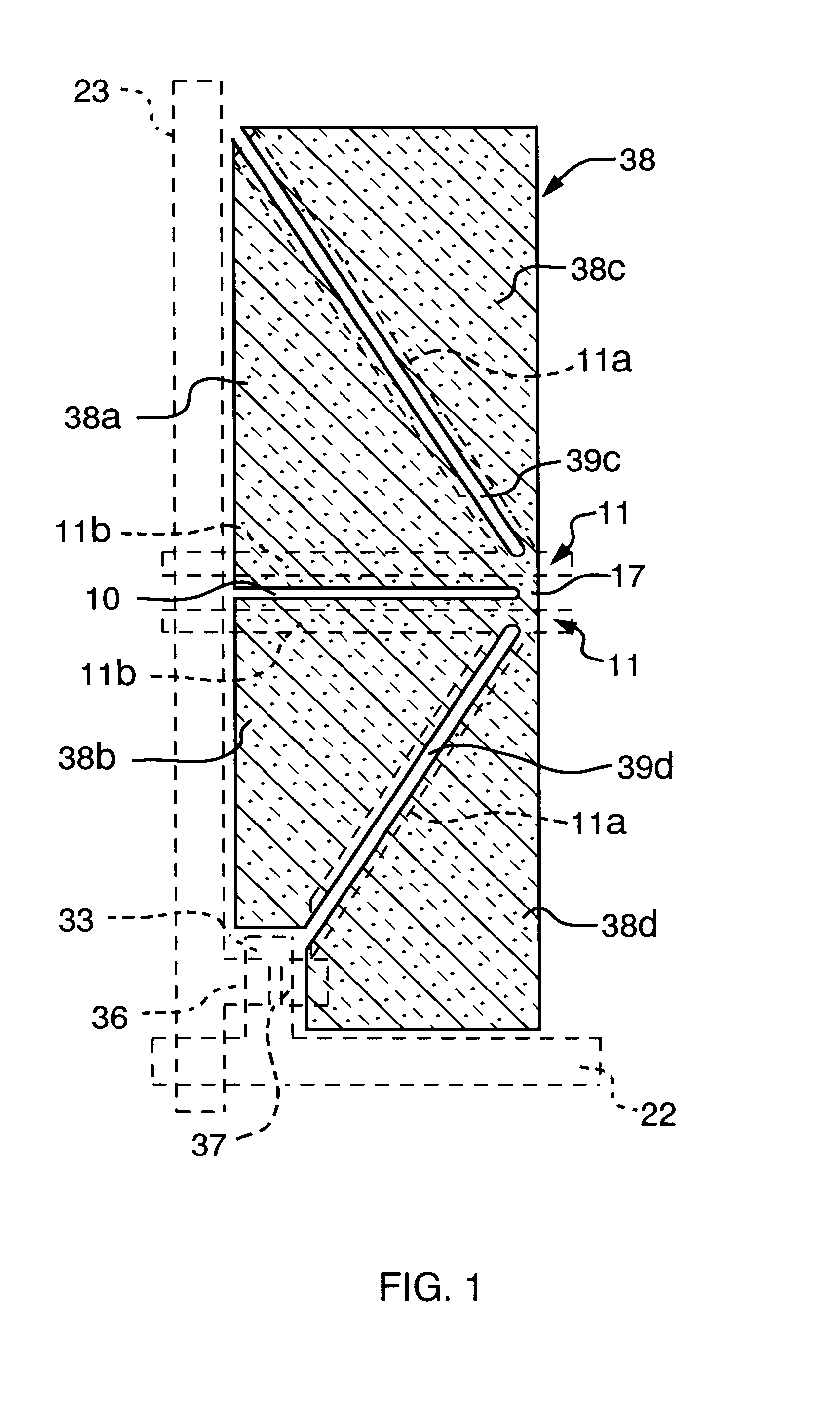
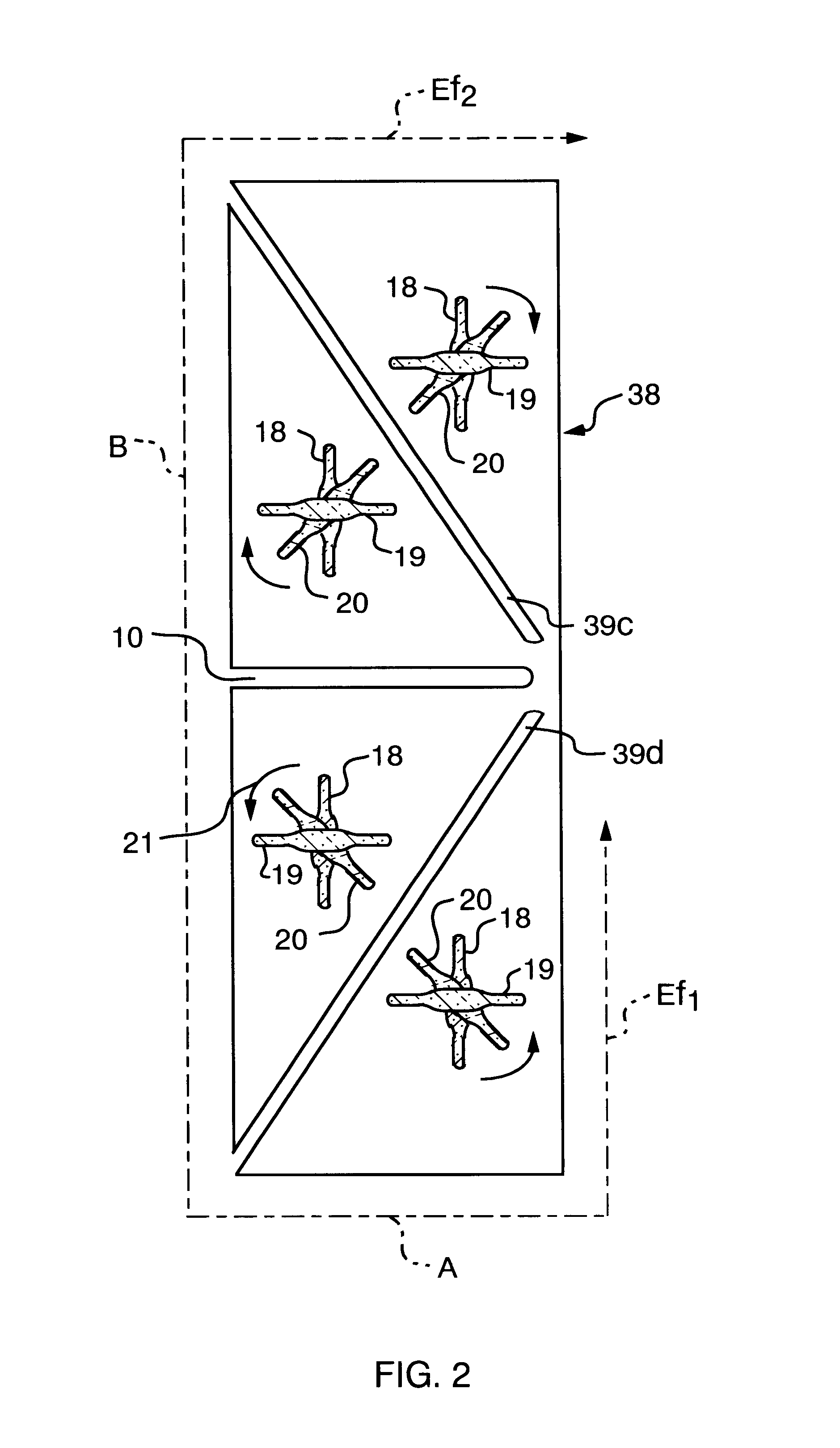
Referring to the drawings, preferred embodiments of the present invention will be explained in detail. FIG. 1 is a plan vie showing essential portions of a liquid crystal display device according to the present invention, and FIG. 2 is a plan view showing the orientation splitting state in the liquid crystal display device in FIG. 1. The basic technology of the orientation splitting in the present embodiment is similar to the technique described in the JP Patent Kokai JP-A-10-20323 explained with reference to FIG. 10.

The liquid crystal display device of the present embodiment differs from the prior-art technology as to the structure of the pixel electrode 38, openings (slits) 39 and 10 and the control electrode 11 shown in FIG. 1, the directions of orientation of the liquid crystal molecules 18 on the side of the pixel electrode, the liquid crystal molecules 19 on the control electrode side and the liquid crystal molecules 20 of the intermediate layer, and as to the arrangement of t...

second embodiment

FIG. 3 is a plan view showing essential portions of the liquid crystal display device according to the present invention. The basic technology of the orientation splitting in the present embodiment is also similar to the technology explained with reference to FIG. 10.

In the present embodiment, the pixel electrode 38 is formed with an opening (first opening or slit) 10 extending substantially parallel to the gate line 22 for splitting the pixel electrode 38 in two in the extending direction of the drain line 23, an opening (second opening or slit) 39c and another opening (third opening or slit) 39d extending from near the end of the opening 10 towards the drain line 23 at a pre-set angle in a direction away from the drain line 23 for further splitting each of the split regions into two. That is, the four regions 38ato 38d in the pixel electrode 38 are substantially line-symmetrical with respect to the respective shapes of the four regions 38a to 38d in the first embodiment, as a resu...

third embodiment

FIGS.4 and 5 are plan views showing essential portions of the liquid crystal display device in the present invention and a plan view showing the state of orientation splitting in the liquid crystal display device of FIG. 4, respectively. The technique underlying the orientation splitting in the present embodiment is similar to the technique explained with reference to FIG. 10.

Referring to FIG. 4, the pixel electrode 38 is provided with an opening (first opening) 39a and an opening (second opening) 39b crossing each other at a mid portion thereof to split the pixel electrode 38 in substantially four equal (rectangular) portions. End marginal portions of the openings 39a, 39bconstitute electrically conductive portions 17 for electrically connecting the neighboring regions 38a to 38d to one another. As an underlying layer to these openings 38a to 38d, there is provided a control electrode 11 extending substantially to follow the contours of the openings 39a, 39b. The control electrode ...


PUM


Abstract

A liquid crystal display device can suppress pixel-based gradation fluctuations observed upon change in angle of view with increased size as it meets wide angle of view characteristics required of a large-sized liquid crystal display device. A device in which a liquid crystal material is sealed between a pair of substrates 31, 32, a plurality of pixel electrodes 38 for applying voltage across the liquid crystal material is arranged on the substrate 31, a common electrode 12 for applying a voltage common to the pixel electrodes 38 is arranged on the substrate 32, and in which a gate line 22 and a drain line 23 of a switching element adapted to control the voltage applied across the pixel electrodes 38 are provided for extending substantially at right angles to each other. In the device, orientation of the liquid crystal molecules 18 neighboring to the pixel electrode 38 is perpendicular to that of liquid crystal molecules 19 neighboring to the common electrode 12, while the respective orientations are substantially parallel to the direction of the gate line 22 or that of the drain line 23.

Description

The present invention relates to a liquid crystal display device. More particularly, it relates to a liquid crystal display device in which it is possible to improve orientation characteristics of a liquid crystal material sealed in a space between a pair of substrates facing each other.DESCRIPTION OF THE RELATED ARTIn a conventional liquid crystal display device, a twisted nematic system is widely used. This system has a drawback that the direction of orientation of liquid crystal molecules of an intermediate layer of the liquid crystal layers at the time of voltage application is uniform in a pixel such that the color tone becomes different depending on different angles of view. As means for improving this viewing angle characteristics, there is known an orientation split type liquid crystal display device. In this type of the liquid crystal display device, each pixel is split into plural regions and the direction of orientation of liquid crystal molecules in the intermediate laye...

Claims


Application Information

Patent Timeline
IPC IPC(8): G02F1/13G02F1/1343G02F1/1333G02F1/1337G02F1/136G02F1/1368
CPCG02F1/134336G02F1/133707G02F2001/13373G02F1/13373G02F1/1337
Inventor MATSUYAMA, HIROAKIKOBAYASHI, KAZUMIHIRAI, YOSHIHIKOISHII, TOSHIYAMURAI, HIDEYASUZUKI, MASAYOSHI
Owner VISTA PEAK VENTURES LLC
Why Eureka
Try Eureka