

Outboard motor cooling and exhaust system
a technology for exhaust systems and outboard motors, applied in the direction of steam power plants, marine propulsion, vessel construction, etc., can solve the problems of narrowing the cylinder bank, affecting performance, and a large wind drag on the engin
- Summary
- Abstract
- Description
- Claims
- Application Information
AI Technical Summary
Benefits of technology
Problems solved by technology
Method used
Image

Examples
Embodiment Construction
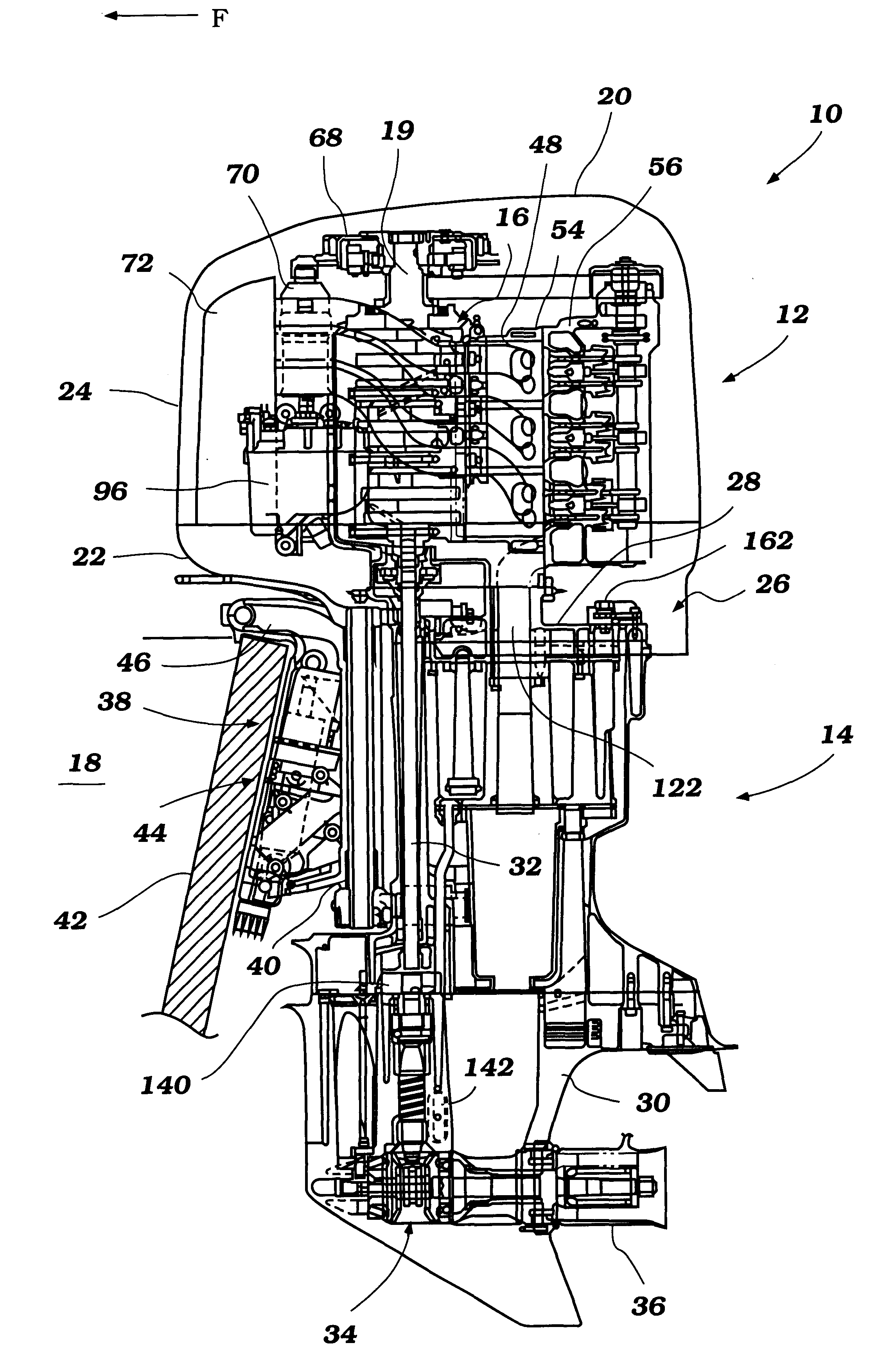
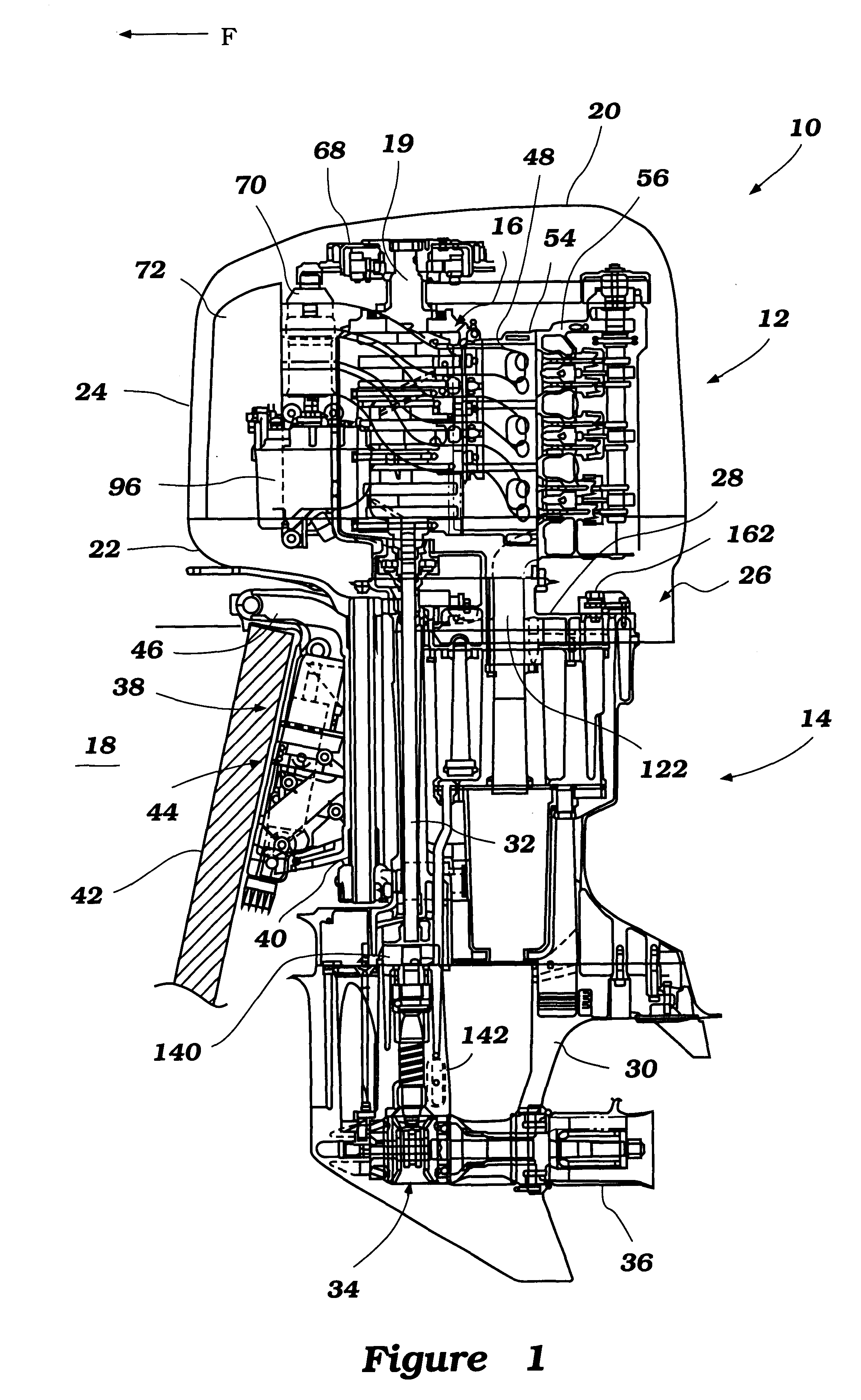
With reference initially to FIG. 1, an outboard motor, indicated generally by the reference numeral 10, is illustrated therein. The illustrated outboard motor advantageously incorporates an exhaust and cooling system configured in accordance with certain features, aspects and advantages of the present invention. The configuration results in a compact motor construction as well as a simplified assembly process. Although the exhaust and cooling system is described below in connection with the illustrated outboard motor, it should be understood that certain features, aspects and advantages of the present invention can also be used in other application, such as, for example, but without limitation, stern-driven watercraft and a variety of other land-based vehicle and engine applications.
The illustrated outboard motor 10 generally comprises a power head 12 and a drive shaft housing 14. The power head 12 preferably contains an internal combustion engine 16 that is used to power a watercra...
PUM
 Abstract
Description
Claims
Application Information