Viewing optical instrument having roof prism and a roof prism

a technology of optical instruments and prisms, applied in the field of viewing optical instruments, can solve the problems of inability to reduce phase differences sufficiently, and determining whether the deterioration of images to be viewed is caused

Inactive Publication Date: 2001-10-16
ASAHI KOGAKU KOGYO KK
View PDF3 Cites 8 Cited by
  • Summary
  • Abstract
  • Description
  • Claims
  • Application Information

AI Technical Summary

Problems solved by technology

To the contrary, the image to be viewed can be deteriorated in an optical system having a roof prism or the like in which the pupil is split by the edge line, due to wavefront aberrations caused by a difference in the polarization state between the lights emitted from the pair of reflection surfaces.
However, it has been found that the metal coating layer cannot sufficiently reduce the phase difference, particularly in accordance with an increase in the machining precision of the roof prism.
Namely, if the machining precision is not high enough, it cannot be determined whether the deterioration of the image to be viewed is caused by the face angle error or by the phase difference.
Condition (1) was obtained through experimentation, and if condition (1) is not satisfied, even if a multiple-layer coating is provided, image quality is decreased and the effect of a reduction in the amount of change in the phase difference before and after reflection cannot be confirmed.
In an optical system (or the roof prism) in which the machining precision of the nominal face angle of the roof prism is not within 90.degree..+-.10", it cannot be confirmed whether the amount of change in the phase difference before and after reflection is reduced by the presence of the dielectric layers since the image is considerably deteriorated when the dimensional precision of the nominal face angle is not good.

Method used


Image

  • Viewing optical instrument having roof prism and a roof prism
  • Viewing optical instrument having roof prism and a roof prism
  • Viewing optical instrument having roof prism and a roof prism

Examples


first embodiment

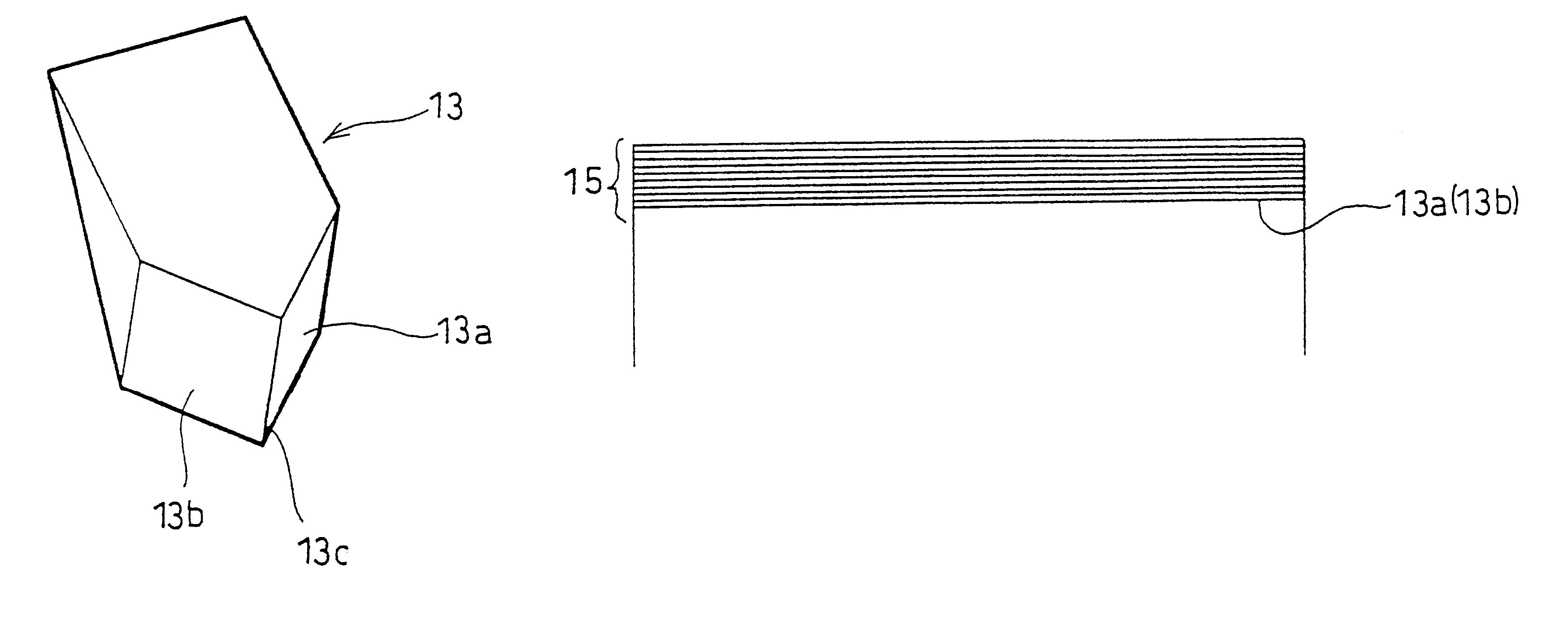
The dielectric layer 15 shown in FIG. 5 is composed of 9 layers superimposed on the roof prism 13. Table 1 below shows numerical data of the When the extinction coefficient K is 0 (K=0), no absorption of light occurs.

Monitor wavelength;550 nm

Refractive index of roof prism: 1.5181 (Material Type: BK7)

Accuracy of roof prism face angle: 90.degree..+-.5" (.epsilon.=5")

Diameter D(mm) of light flux in section, perpendicular to the direction of incidence thereof, incident on the total reflection surfaces: 6 mm

D.times..epsilon.=30 (mm.multidot.seconds)

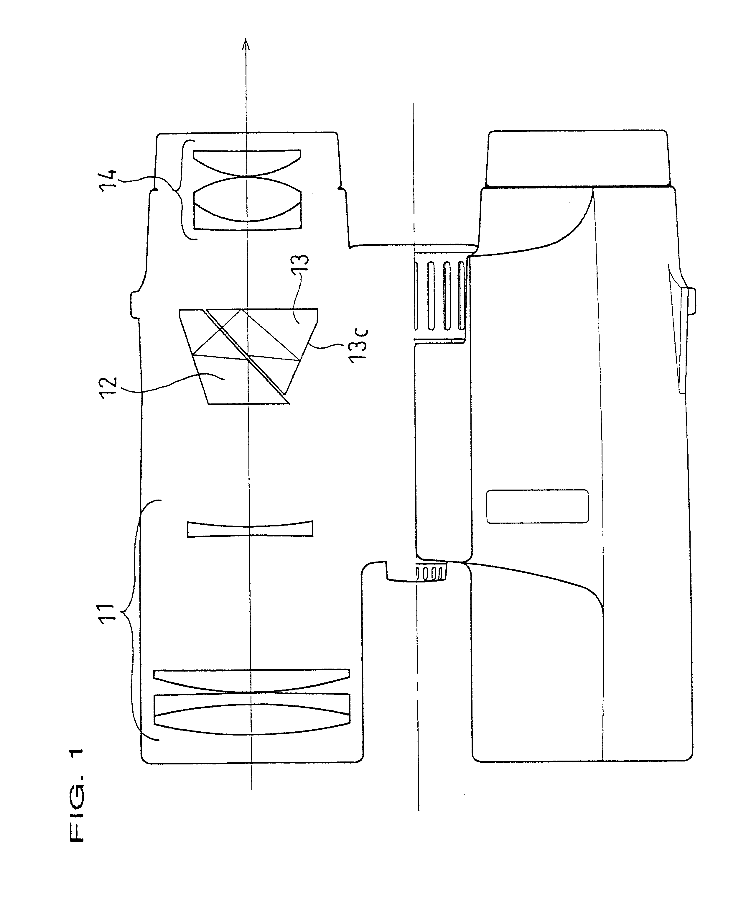
FIG. 6 shows a reflectance R of each wavelength when the light flux which is incident on the reflection surface of the roof-prism 13 through the objective lens 11 at an angle of incidence of -1.degree. with respect to the optical axis of the lens 11 (at an incident angle of 47.74.degree. on the reflection surface) in the first embodiment. The reflectance of 100% is obtained in the entire wavelength range (400 to 700 nm) of the visible light. ...

embodiment 2

The dielectric layer 15 shown in FIG. 5 is comprised of 9 layers superimposed on the roof prism 13. Table 2 shows the numerical data for the second embodiment thereof.

Monitor wavelength;550 nm

Refractive index of roof prism;1.489 (Material Type: BK5)

Accuracy of roof prism face angle;90.degree..+-.5" (.epsilon.=5")

Diameter D(mm) of light flux in section, perpendicular to the direction of incidence thereof, incident on the total reflection surfaces: 6 mm

D.times..epsilon.=30 (mm.multidot.seconds)

FIG. 10 shows a reflectance R of each wavelength when the light flux which is incident on the reflection surface of the roof-prism 13 through the objective lens 11 at an angle of incidence of +0.47.degree. with respect to the optical axis of the lens 11 (at an incident angle of 49.21.degree. on the roof-prism) in the second embodiment. The reflectance of 100% is obtained in the entire wavelength range (400 to 700 nm) of the visible light. FIG. 11 shows the change in the phase differences for the...

embodiment 3

The dielectric layer 15 shown in FIG. 5 is comprised of 9 layers superimposed on the roof prism 13. Table 3 shows numerical data thereof.

Monitor wavelength: 550 nm

Refractive index of roof prism: 1.499 (Material Type: BK7)

Accuracy of roof prism face angle: 90.degree..+-.5" (.epsilon.=5")

Diameter D(mm) of light flux in section, perpendicular to the direction of incidence thereof, incident on the total reflection surfaces: 6 mm

D.times..epsilon.=30 (mm.multidot.seconds)


PUM


Abstract

A viewing optical instrument has a roof prism which is provided with a pair of reflection surfaces intersecting at a nominal face angle of 90°, wherein the pupil is split by an edge line of the reflection surfaces of the roof prism. The reflection surfaces are provided with a multiple-layer coating which does not absorb visible light. A change in the phase difference produced between light incident on one of reflection surfaces located on opposite sides of an edge line of the roof prism and emitted from the other reflection surface, and light incident on the right reflection surface and emitted from the left reflection surface is restricted to reduce wavefront aberrations to thereby improve the quality of an image to be viewed. A roof prism used in the optical instrument is also disclosed.

Description

1. Field of the InventionThe present invention relates to a viewing optical instrument having a roof prism, which is adapted to invert an object image in the vertical and horizontal directions. The present invention also relates to a roof prism.2. Description of the Related ArtIn viewing optical instruments, such as a monocular or binocular telescope, those using a roof prism having a pair of reflection surfaces intersecting at a nominal face angle of 90 degrees can be made small since an object image formed by an objective optical system can be inverted in the vertical and horizontal directions by a single roof prism. However, since the pupil of the objective optical system is split by an edge line of the reflection surfaces, the face angle must be highly precise. If the face angle is not accurate, a viewable double image occurs.As is well known, in the case where light is reflected by a reflection surface, a phase difference is produced between two orthogonal P-polarized and S-pol...

Claims


Application Information

Patent Timeline
Patent Type & Authority Patents(United States)
IPC IPC(8): G02B5/04
CPCG02B5/04
Inventor ITO, TAKUNOGUCHI, MASATO
Owner ASAHI KOGAKU KOGYO KK
Why Eureka
Try Eureka