Surface light source device and liquid crystal display

a surface light source and liquid crystal display technology, which is applied in the direction of lighting and heating apparatus, instruments, machines/engines, etc., can solve the problems of reducing the display quality of the liquid crystal display incorporating the light source device, reducing the angular range of the emitting surface, and unable to meet the requirement, so as to improve the display quality of the liquid crystal display, narrow the visual field of the surface light source device, and increase the brightness

Inactive Publication Date: 2001-10-30
ENPLAS CORP +1
View PDF17 Cites 19 Cited by
  • Summary
  • Abstract
  • Description
  • Claims
  • Application Information

AI Technical Summary

Benefits of technology

Accordingly, it is an object of the present invention to accomplish narrowing of visual field of a surface light source device or increase of the brightness by using two

Problems solved by technology

As a result, the angular range in which the emitting surface is observed to be luminous is restricted.
This deteriorates the display quality of a liquid crystal display incorporating the light source device.
However, in the above-described well-known usage of prism sheets, it is impossible to satisfy the requirement, i.e., narrowing of the visual field both in the plane verti

Method used


Image

  • Surface light source device and liquid crystal display
  • Surface light source device and liquid crystal display
  • Surface light source device and liquid crystal display

Examples


Embodiment Construction

To briefly describe the features of the embodied examples of the invention, the examples are classified into group I and group II. The graphs of FIGS. 10-31 are described clause by clause. Group I (Examples 1-7) mainly intends clear narrowing of the visual field. Increase of the brightness is also at least considerably accomplished as a result of the narrowing of the visual field.

Group II (examples 8-11) mainly intends to increase the brightness. Narrowing of the visual field is also accomplished at least to some extent.

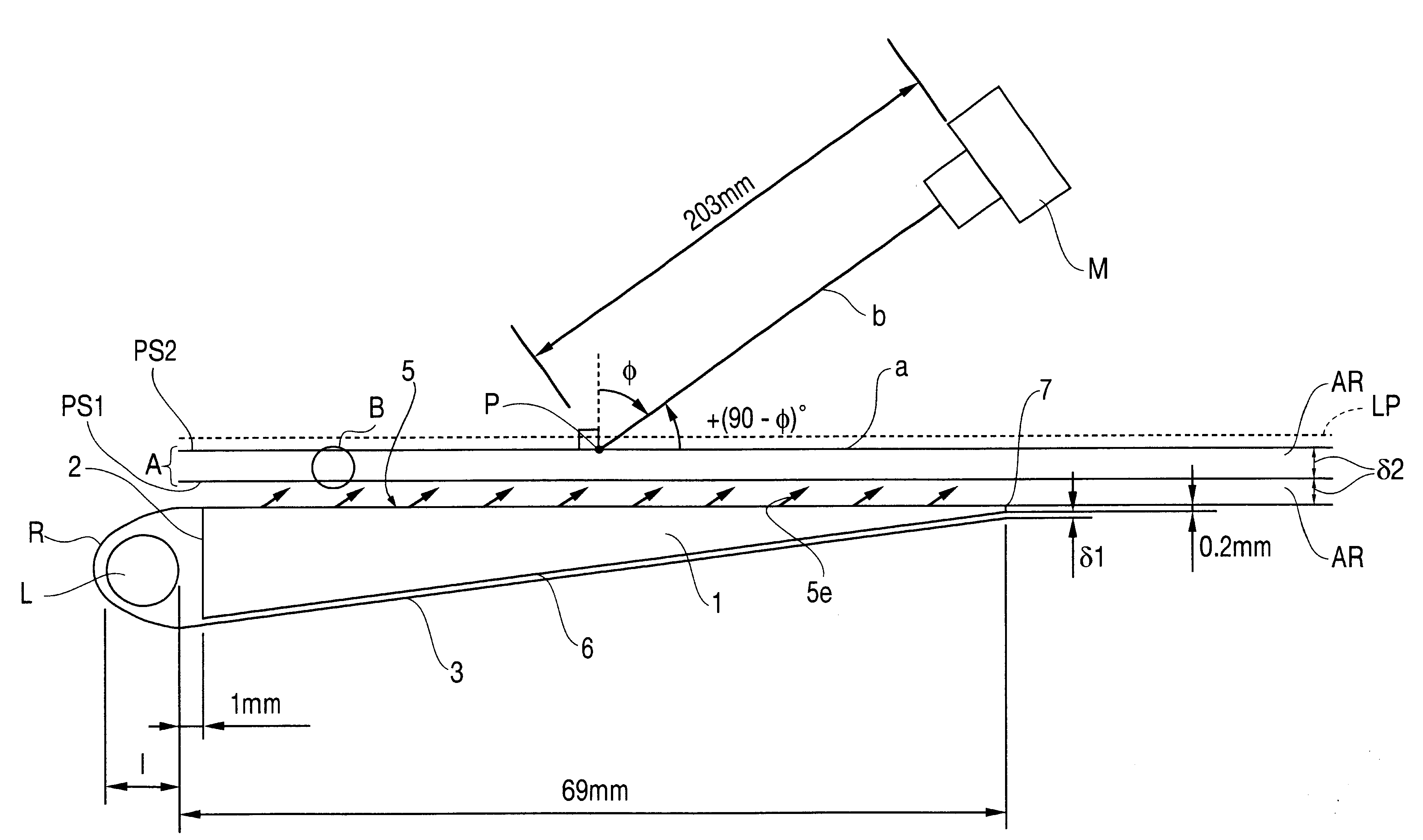
The conditions of all the examples, including the measurement conditions and excluding the direction of arrangement of two prism sheets, orientations (either inward or outward) and vertical angle conditions, have been already described in connection with FIG. 4, which shows the essential structure of the surface light source device of each example. Obviously, where the surface light source device is applied to backlighting arrangement for a liquid crystal display, a ...


PUM


Abstract

A surface light source device has a narrowed visual field and increased brightness. The surface light source device can be applied to a liquid crystal display. The back side of a fluorescent lamp is covered with silver foil. Light emitted from the lamp enters a wedge-shaped light guide plate through its incident surface. The light guide plate is designed so that directional light exits from the guide plate. When the light is guided toward a thin-walled end surface through the light guide plate, the light is scattered, reflected, and undergoes other action. Collimated light flux gradually exits from the exiting surface. The light flux passes through two prism sheets successively. As a result, the direction of propagation of the light is restricted in two dimensions. The light flux of increased brightness is directed to the liquid crystal panel. V-shaped channels formed in the prism faces of the two prism sheets PS1, PS2 are arrayed in two mutually perpendicular directions while facing outward. The prismatic vertical angles of the two sheets PS1, PS2 have various desirable combinations of values. For example, where the first sheet PS1 is disposed vertical to the lamp, the vertical angles of the two sheets PS1, PS2 are preferably 90° and 70°, respectively.

Description

1. Field of InventionThe present invention relates to techniques for narrowing the visual field or increasing the brightness of a surface light source device, by making use of two prism sheets. The present invention is especially advantageously applied to backlighting of a liquid crystal display which is observed preferentially from a certain direction.2. Related ArtA well-known optical device taking the form of a sheet and acting to modify the propagation direction characteristic of a primary light beam supplied from one surface and to cause the beam to exit from the other surface as a secondary light beam is generally known as a prism sheet.Generally, a prism sheet consists of a member in the form of a plate made of an optical material having a surface (or prism face) provided with a number of aligned, repeating V-shaped channels (an array of convex and convex portions). Since this device has a function of modifying directions of light flux having a cross-sectional area correspond...

Claims


Application Information

Patent Timeline
IPC IPC(8): F21V5/00F21V8/00F21V5/02G02F1/1335G02F1/13G02B6/00G02F1/13357
CPCF21V5/02G02B6/0053F21Y2105/00G02B6/0041G02F1/133615
Inventor SASAKO, HIROMIWATAI, KAYOKO
Owner ENPLAS CORP
Why Eureka
Try Eureka