
Plant for feeding paint to a spray application apparatus

a spraying apparatus and paint technology, applied in the direction of liquid spraying apparatus, movable spraying apparatus, coatings, etc., can solve the problems of limiting the ability to move the spraying robot, generating high costs, and reducing the amount of paint types and colours

Inactive Publication Date: 2001-10-30
ABB FLEXIBLE AUTOMATION AS
View PDF6 Cites 14 Cited by
  • Summary
  • Abstract
  • Description
  • Claims
  • Application Information

AI Technical Summary

Benefits of technology

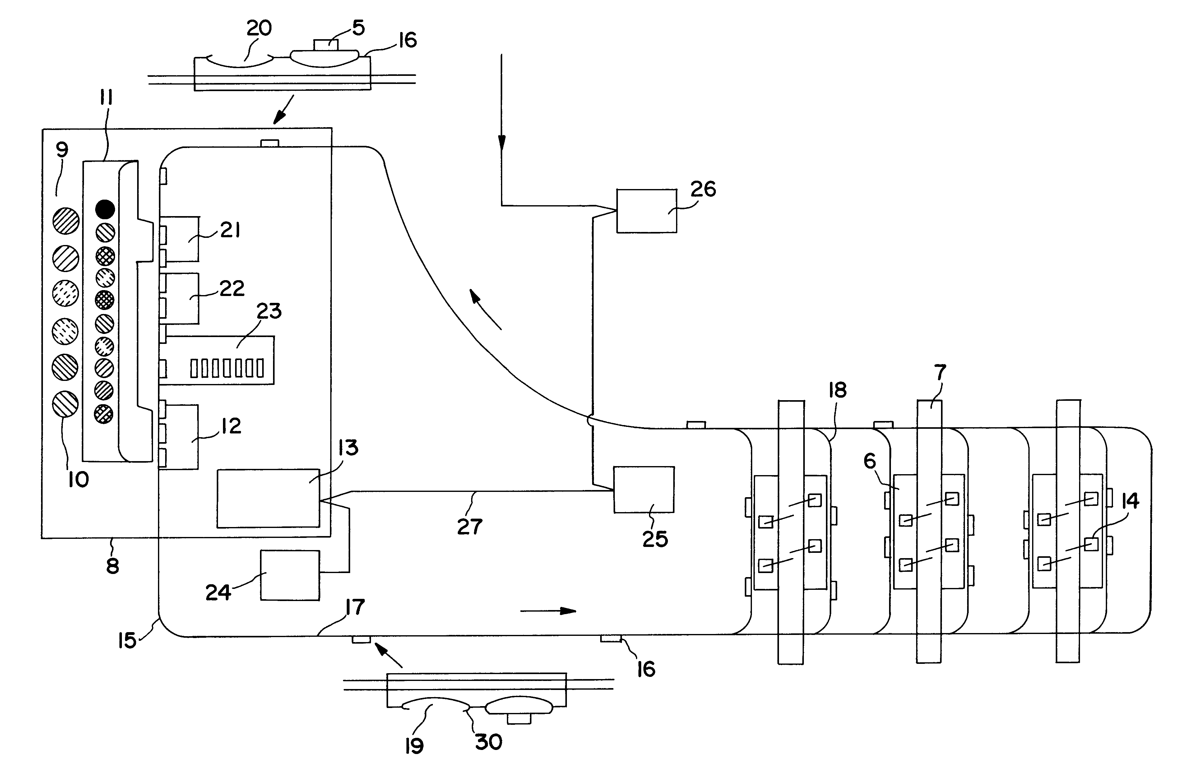
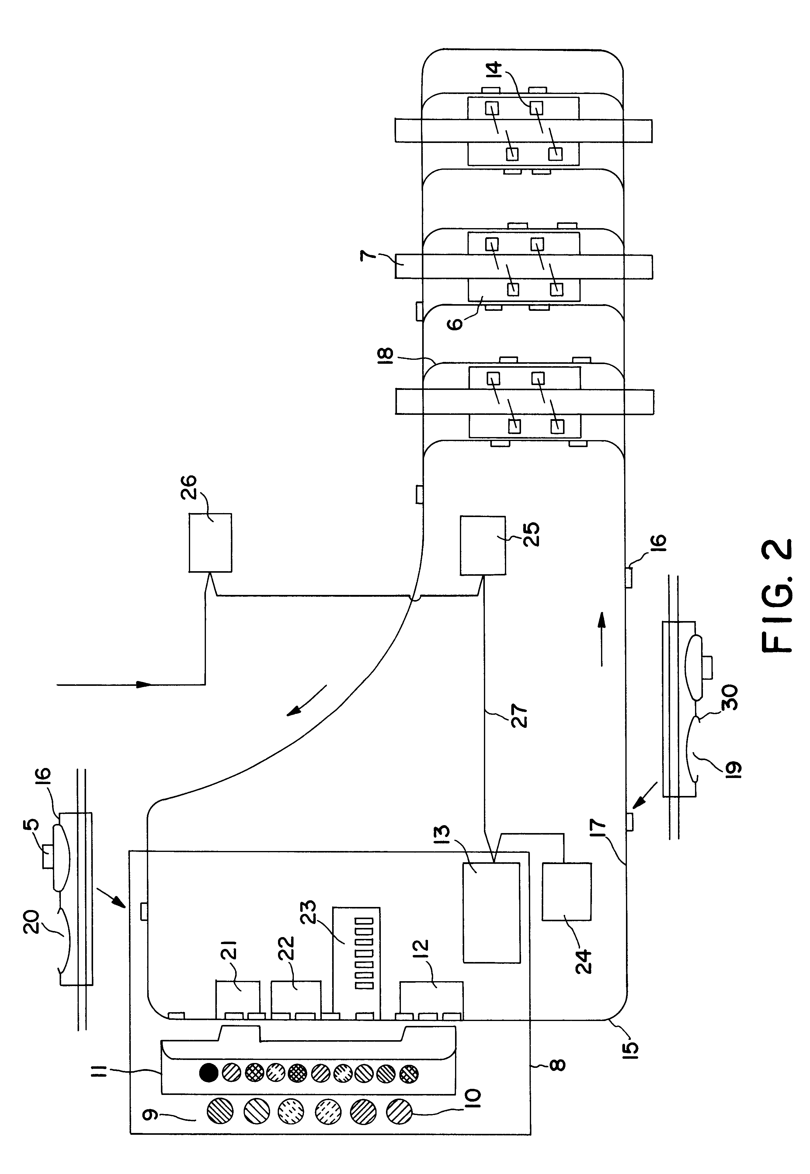
Thus, the invention is based on the idea of moving said unit providing paint all the way to the very spray application apparatus, so that the connection thereof to the spray nozzle during the application will be short, and to replace the units containing paint located at a large distance to the spray application apparatus and the ring conduits running therefrom to the spray application apparatus by a station with containers filled with paint and a transport device for transporting the containers to and away from the spray application apparatus Long ring conduits, which may be plugged and which require a comparatively high pump power, especially when pumping water born paints of a high viscosity, are hereby avoided. The spray application apparatus will neither be burdened by a great amount of hoses and valves, thanks to the centralized paint selection made possible here in said station and not at the spray application apparatus. There is neither any insulating problem when using water born paints in connection with electrostatic painting. Other advantages of a plant of this type are that it requires a smaller volume in the factory or the like in which it is arranged, and it increases the flexibility for rebuilding and modifications in the production. The loss of paint will also be smaller than in the plants already known.
According to another preferred embodiment of the invention said station has a supply of paints of different types and / or colours, it has also paint handling members in the form of members for filling empty containers with paint, and the second control unit is arranged to control the filling members according to data introduced into the control device and relating to future container exchanges. Conduits required may be made considerably shorter thanks to the centralized colour selection obtained in this way, so that the pumps required are consuming considerably less power and a lower pressure fall is required, and it will also be easier to remove depositings in the conduits.
According to another preferred embodiment of the invention the transport device comprises a transport track running in a loop from said station to the region of said apparatus and back to the station for transporting said containers, and said means for transporting containers to and away from the apparatus comprises carriages having members for receiving containers and members for driving these to move along the transport track. A change of paint type and / or colour or filling of paint in said apparatus may easily take place thanks to the arrangement of such carriages for container transport.
According to another preferred embodiment of the invention each carriage has at least two said receiving members, a first one intended to be provided with a container during the movement of the carriage from the station to the apparatus and empty during the movement of the carriage from the apparatus to the station and a second one adapted to be empty during the movement of the carriage from the station to the apparatus and have an exchanged container delivered by the apparatus received therein during the movement of the carriage from the apparatus to the station. A carriage may by designing it in this way both transport a container to the spray application apparatus and when returning to the station carry the container exchanged therealong, at the same time as the exchange of containers in the apparatus will be simple, since the second receiving member is free when the carriage arrives to the apparatus, so that the apparatus may first of all deliver the container to be exchanged to the carriage and then without any problem fetch the new container from the carriage.
According to another preferred embodiment of the invention the plant is adapted to feed paint to a plurality of said spray application apparatuses, and the transport track has a plurality of loops for feeding spray application apparatuses arranged in parallel. A greater amount of spray application apparatuses may in this way be provided with a desired paint emanating from a station. It is then advantageous that the transport track has a joint loop part for transport of containers to and away from the different spray application apparatuses and parallel outer loops connected thereto and running to separate spray application apparatuses. The construction of the plant is hereby simplified and the cost counted per spray application apparatus is hereby reduced. In the particular case of painting vehicle bodies through spray robots the plant may hereby by simple means provide a number of working stations in the form of spray booths, which each contains several spray robots, with the paint to be applied on the vehicle body located in each individual spray booth in a given instant.

Problems solved by technology

This means several considerable disadvantages, primarily when the amount of possible paint types and colours to be sprayed by the spray robot is increasing.
At a greater such amount a great amount of hoses running to and from the spray robot are required, both generating high costs and restricting the ability to move of the spray robot.
Furthermore, as already mentioned, a large number of valves and control members for controlling the latters is at the same time needed.
Another disadvantage arises when the paints are water born, which are more and more used, since these paints have a higher viscosity than paints on oil base, so that a higher pump pressure is required for pumping the paint in the spray robot and the risk for depositing and plugging of hoses is also increased.
Furthermore, a considerable problem to obtain electrical insulation between the paint sources and the spray nozzle also arises in electrostatic painting while using water born paints and said ring conduits.

Method used


Image

  • Plant for feeding paint to a spray application apparatus
  • Plant for feeding paint to a spray application apparatus
  • Plant for feeding paint to a spray application apparatus

Examples


Embodiment Construction

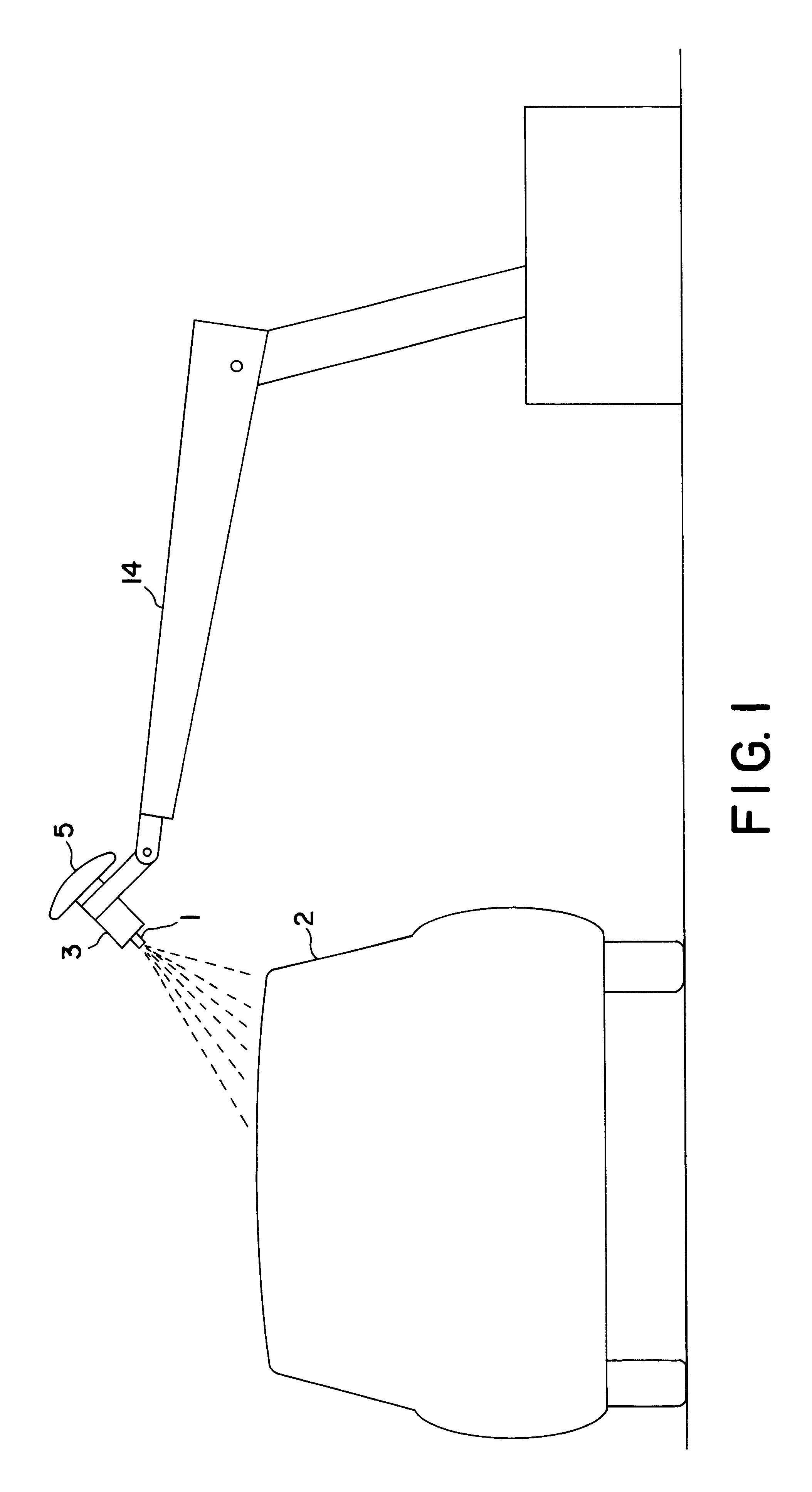
An apparatus for spray application of paint in the form of a spray painting robot is very schematically illustrated in FIG. 1, and this is adapted to be used together with a plant for feeding paint thereto according to the invention. This robot has different robot arms hingedly interconnected and a spray nozzle 1 in the form of a gun is arranged outermost on the last robot arm, but there may also be a question of a bell, and this spray nozzle is adapted for spray application of atomized paint on an object 2, here a vehicle body. The spray nozzle is connected to an arrangement 3 schematically indicated for atomizing the paint delivered to the spray nozzle 1 through a conduit from a container 5 containing paint and located in the immediate vicinity of the spray nozzle. Different conduits for example supply of compressed air for electric control of parts including in the apparatus have been omitted in FIG. 1 for the sake of simplicity, and parts thereof having nothing to do with the in...


PUM


Abstract

A plant is adapted to feed paint to robots for automatic spray application of paint on objects provided with a container (5) made loosenable and removable from the robot for exchange for another such container when there is a desire to have more paint in the container and / or change paint. The plant has a station (8) with containers filled with paint, a transport device (15-18) with means (16) for transporting a container containing paint from said station when said desire arises to the robot and deliver this thereto as well as means adapted to receive a container to be exchanged from the robot and transport it away for taking care thereof.

Description

FIELD OF THE INVENTION AND PRIOR ARTThe present invention relates to a plant for feeding paint to at least one apparatus having a nozzle and being adapted for automatic spray application of paint on objects, said plant having a unit providing paint arranged to be connected to the nozzle during the application for providing it with paint as well as an arrangement coordinated with said unit for enabling change of paint and / or filling of paint in the unit connected to the spray nozzle.Such a plant may be arranged to provide different types of spray application apparatuses with paint within a number of different fields of use, but for illuminating, but not in any way restricting the invention, the use of such a plant for feeding paint to one or more spray application robots for painting objects, such as vehicle bodies, will hereinafter mainly be discussed, but the invention comprises also supply of paint to such apparatuses in the form of so called painting machines. "Paint" is here to ...

Claims


Application Information

Patent Timeline
IPC IPC(8): B05B9/04B05B9/047B05B12/14B05B12/00
CPCB05B9/047B05B12/1463B05B13/0452
Inventor ANFINDSEN, OLE ARNT
Owner ABB FLEXIBLE AUTOMATION AS
Learn More