M-shaped boat hull

a hull and hull technology, applied in the field of watercraft, can solve the problems of weak propeller wave action and noise pollution, damage to the foundations at the water/land interface, and the less effective rudder

Inactive Publication Date: 2001-11-13
MANGIA ONDA
View PDF5 Cites 25 Cited by
  • Summary
  • Abstract
  • Description
  • Claims
  • Application Information

AI Technical Summary

Benefits of technology

It is a further objective in certain embodiments of the present invention to provide a powerboat having a relatively narrow central displacement body and planing wings to operate efficiently at low speed in the displacement mode, while requiring less power for efficient transfer into the planing mode, thereby providing efficient planing at high speed.
It is a further objective to use the multi-hull catamaran with M-shaped hulls as a means of expanding the size of the single-hull watercraft with M-shaped hull described above without significant increase in the width and height of the wing channel entrance. This is important for ensuring a tight spiraling of the bow wave for efficient entrapment and forming of the entering air through the wing channel achieved with the single-hull watercraft with M-shaped hull described above. These objectives are achieved with a multi-hull watercraft having M-shaped hulls as subsequently described and claimed.

Problems solved by technology

When the bow wave does so, it has sufficient energy to threaten other nearby boats and cause damage to foundations at the water / land interface in narrow waterways.
In addition, engines mounted on the stem of the boat generate strong propeller wave action and noise pollution, which are especially objectionable to residences and / or commercial buildings located near the water / land interface.
These problems are accentuated when boats operating at low speeds are required to make sharp-angle turns in narrow waterways, such as in the canals of Venice, Italy.
Because a rudder is less effective under such conditions, an articulating outboard motor (or propeller), which accentuates the generation of waves and noise pollution, may be required.
1. Conventional power boats are designed as either: (a) displacement boats, efficient at low speeds but with sufficient power and planing surface to transcend the hull speed limits; or (b) planing boats, inefficient at low speed but with sufficient power and planing surface to transcend the hull speed limits;
2. As mentioned above, bow waves generated by a boat move forward initially at the boat speed, but thereafter at decreasing speed due to friction, leading to potentially destructive bow waves moving laterally away from the boat;
3. A significant portion of propulsion energy is lost when converted into wave energy, leading to inefficiency;
4. Bow and stern waves plus stern-mounted propeller wave action generated by boats operating at high speed can cause serious damage to other boats and to foundations at the water / and interface in narrow waterways and small lakes; and
5. Wave, noise, and air pollution generated by conventional displacement boats powered by internal combustion engines are accentuated with an articulating outboard motor or propeller.
Although increasingly popular, both sail and motor powered conventional catamarans suffer important disadvantages.
Among other things, motor powered catamarans generate large bow waves at high speeds which threaten other nearby boats and foundations at the water / land interface.
In addition, they generate substantial external noise pollution.
Furthermore, neither motor or sail powered catamarans recover energy from the bow waves and thus they remain displacement boats and this limits propulsion efficiency at higher speeds.

Method used


Image

  • M-shaped boat hull
  • M-shaped boat hull
  • M-shaped boat hull

Examples


Embodiment Construction

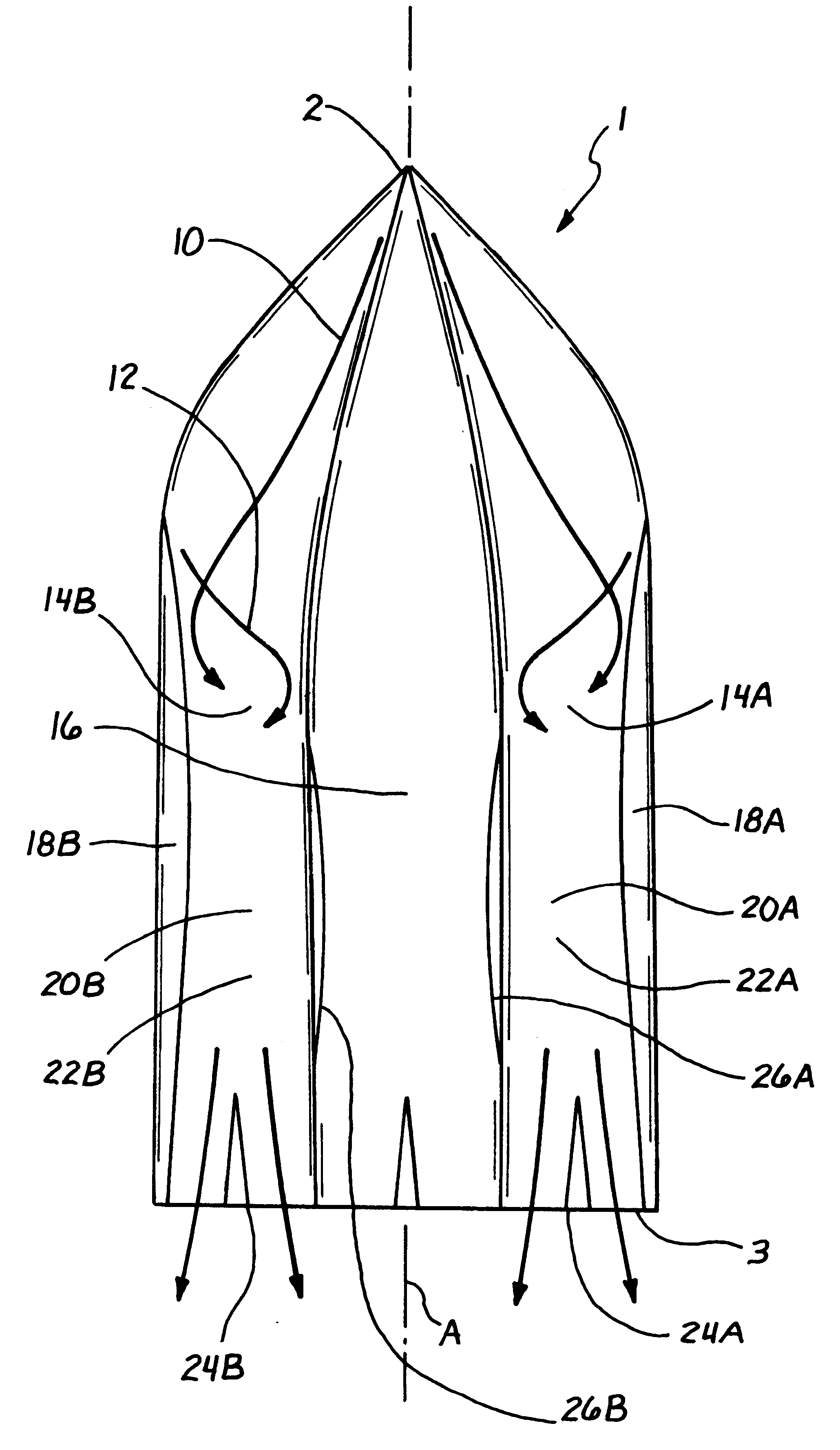
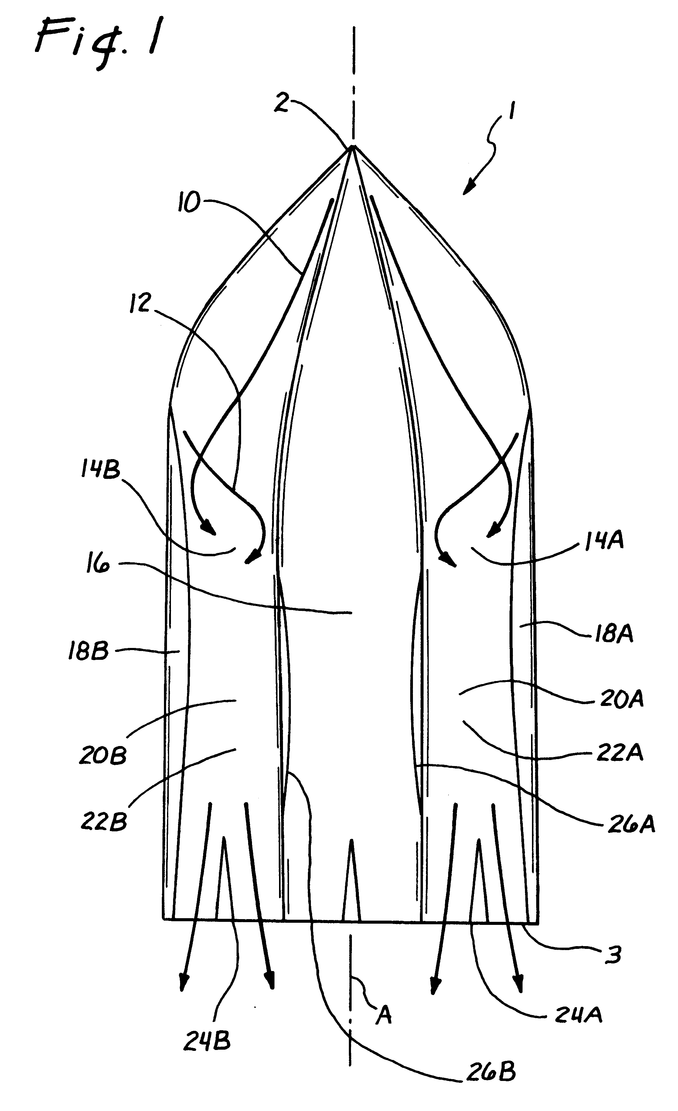
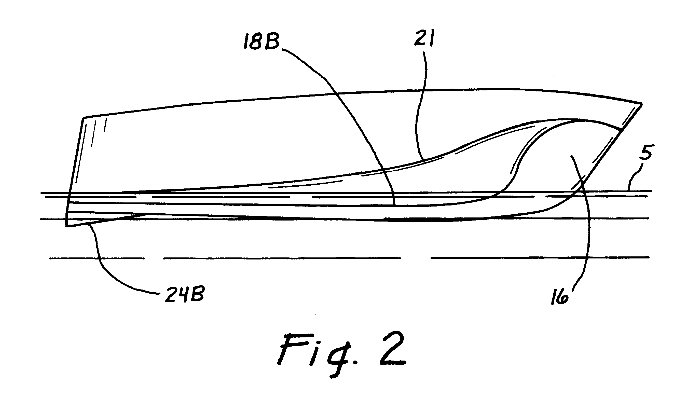
The present invention is predicated on the realization that a boat propelled by motor or sail generates bow waves containing energy. With a conventional hull design, this energy is not only lost, thereby reducing efficiency, but also threatens other boats and damage to structures at the water / land interface. The "M-shaped" hull of the present invention recaptures the bow waves not only to protect other boats and structures at the water / land interface, but also to enhance boat efficiency. In the following detailed description, certain preferred embodiments of the present invention are described structurally first and then the general operation is provided.

Referring initially to FIGS. 1 and 2, the present invention provides a powerboat comprising an "M-shaped" hull 1 having a fore end 2, and aft end 3, and a longitudinal axis (designated by a reference number A in FIG. 1) extending between the fore end 2 and the aft end 3. The hull 1 includes a displacement body 16, which is preferabl...


PUM


Abstract

The present invention relates to a watercraft having a wave suppressing "M-shaped" hull design. The hull comprises a central displacement body flanked by two downwardly extending outer skirts. The outer skirts are attached to the displacement body by planing wings having wing channels. The bow wave is directed into the wing channels, thereby increasing planing efficiency and reducing the effect of such waves on other boats and the shoreline. One embodiment takes the form of a twin-hull catamaran with two M-shaped hulls and four arcuate channels for containing the spiraling bow waves from the two central displacement bodies, thus to increase lateral stability and to suppress boat waves to protect nearby boats and structures at the water / land interface.

Description

1. Technical FieldThis invention relates generally to watercraft, and more particularly to a motorboat or sailboat form of watercraft having at least one displacement body that produces a bow wave.2. Description of Related ArtMotor and sail powered displacement boats generate a bow wave, followed by a trough and stem wave, due to hull form and friction. For a displacement boat, the bow wave increases in amplitude with boat speed until propulsion power is insufficient to climb the wave (i.e., the hull speed limit). The bow wave, when generated, initially moves forward at the hull speed, but eventually loses speed and moves at an angle away from the hull. When the bow wave does so, it has sufficient energy to threaten other nearby boats and cause damage to foundations at the water / land interface in narrow waterways. In addition, engines mounted on the stem of the boat generate strong propeller wave action and noise pollution, which are especially objectionable to residences and / or com...

Claims


Application Information

Patent Timeline
Patent Type & Authority Patents(United States)
IPC IPC(8): B63B1/04B63B1/00
CPCB63B1/042F05B2220/50
Inventor ROBINSON, CHARLES W.BURNS, III, WILLIAM F.
Owner MANGIA ONDA
Why Eureka
Try Eureka