
Communications network

a communication network and network technology, applied in the field of communication networks, can solve problems such as packet delay

Inactive Publication Date: 2001-11-13
INTPROP ASSET MANAGEMENT LLC
View PDF8 Cites 60 Cited by
  • Summary
  • Abstract
  • Description
  • Claims
  • Application Information

AI Technical Summary

Benefits of technology

According to embodiments of the present invention, more or less sophisticated algorithms may be incorporated in each ONU to predict future buffer fullness based upon a recent history of buffer fullness and permitted upstream capacity. As a secondary benefit, the ability for example to pre-empt a reduced requirement in a future cycle helps to minimise wastage of assigned capacity and releases capacity to other ONUs earlier than may have been possible with a conventional demand assignment protocol. This helps to minimise delays to transmission of data in subsequent cycles, particularly during times of high PON utilisation, so increasing the overall efficiency of the PON.
In some PONs, it may prove advantageous to centralise the algorithms for prediction of future ONU capacity requirements at the OLT. This incurs a greater processing overhead on the OLT, but advantages may accrue from the access that the OLT has to information from all the ONUs connected to the PON. Rather than sending requests to the OLT for capacity already calculated using a prediction algorithm, an ONU may simply supply factual information to the OLT regarding buffer fullness at the time of its upstream transmission slot, for example, and allow the OLT to perform the calculation of expected capacity requirements using that information and information made available over previous cycles. Besides minimising variation in data transmission delay at an ONU, algorithms centralised in the OLT may enable a PON to recover more quickly from periods of very high loading during which data may have been delayed at ONUs, the OLT potentially being able to optimise the recovery for the benefit of the whole PON more quickly than if some of the functionality required were devolved to the ONUs. In such an arrangement, the OLT has the benefit of knowing the actual buffer fullness of each ONU, rather than being presented with a series of demands for capacity which may or may not correspond to actual buffer fullness at that time.

Problems solved by technology

A typical "star" PON configuration does not permit ONUs to communicate directly with each other and to decide among themselves which one will next be allowed to send data upstream to the OLT.
In some time slots, not all the allocated capacity may be used by the ONU, while in others the ONU may have more packets in its buffer than the allocation will allow to be transmitted in that cycle, leading to packet delay.

Method used


Image

  • Communications network
  • Communications network
  • Communications network

Examples


Embodiment Construction

Embodiments of the invention will now be described in more detail, by way of example only, with reference to the accompanying drawings in which:

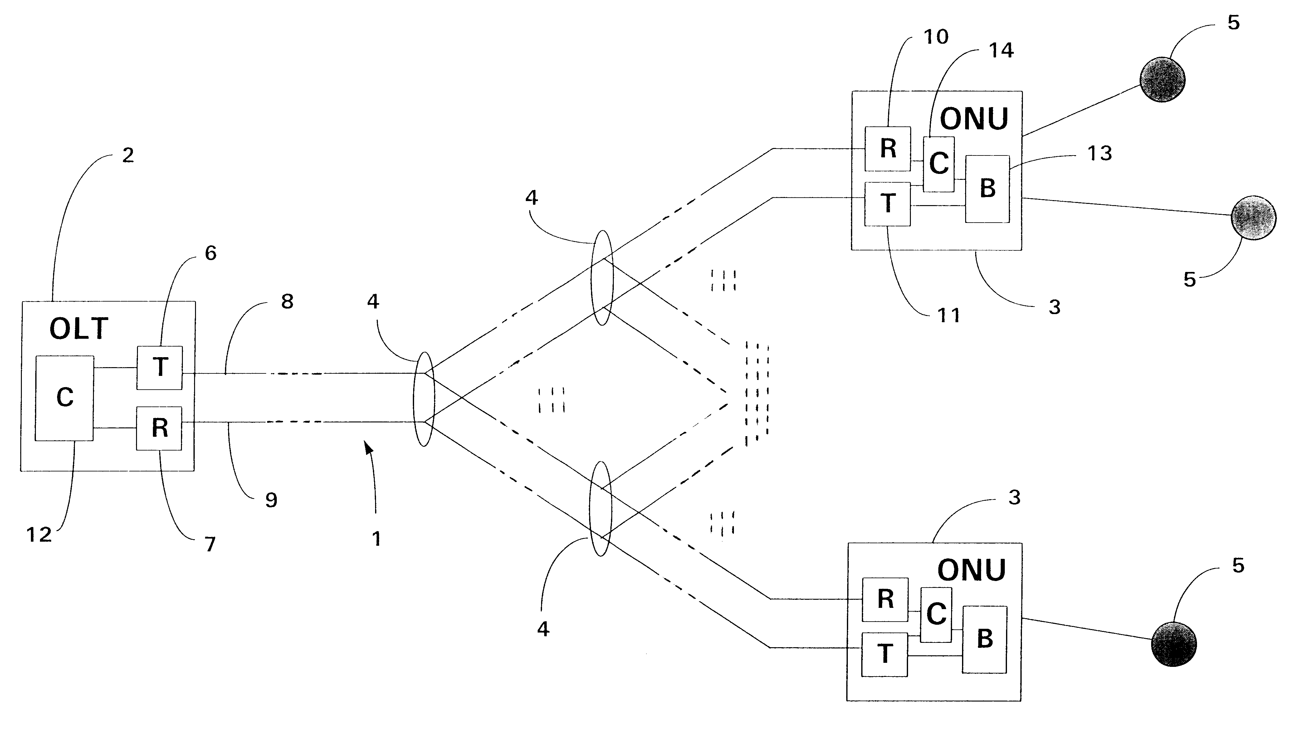
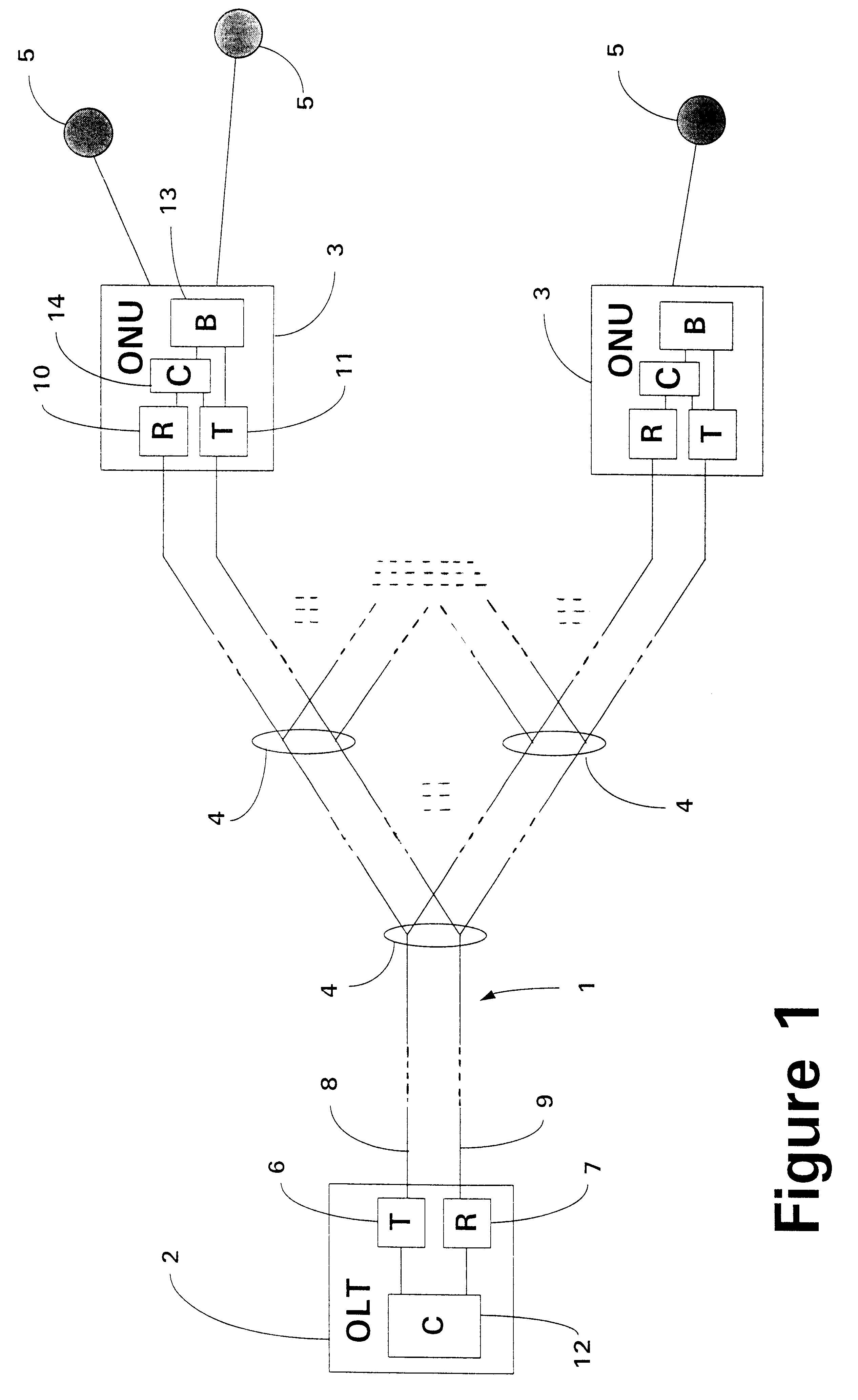
FIG. 1 shows the configuration of a typical known local access PON;

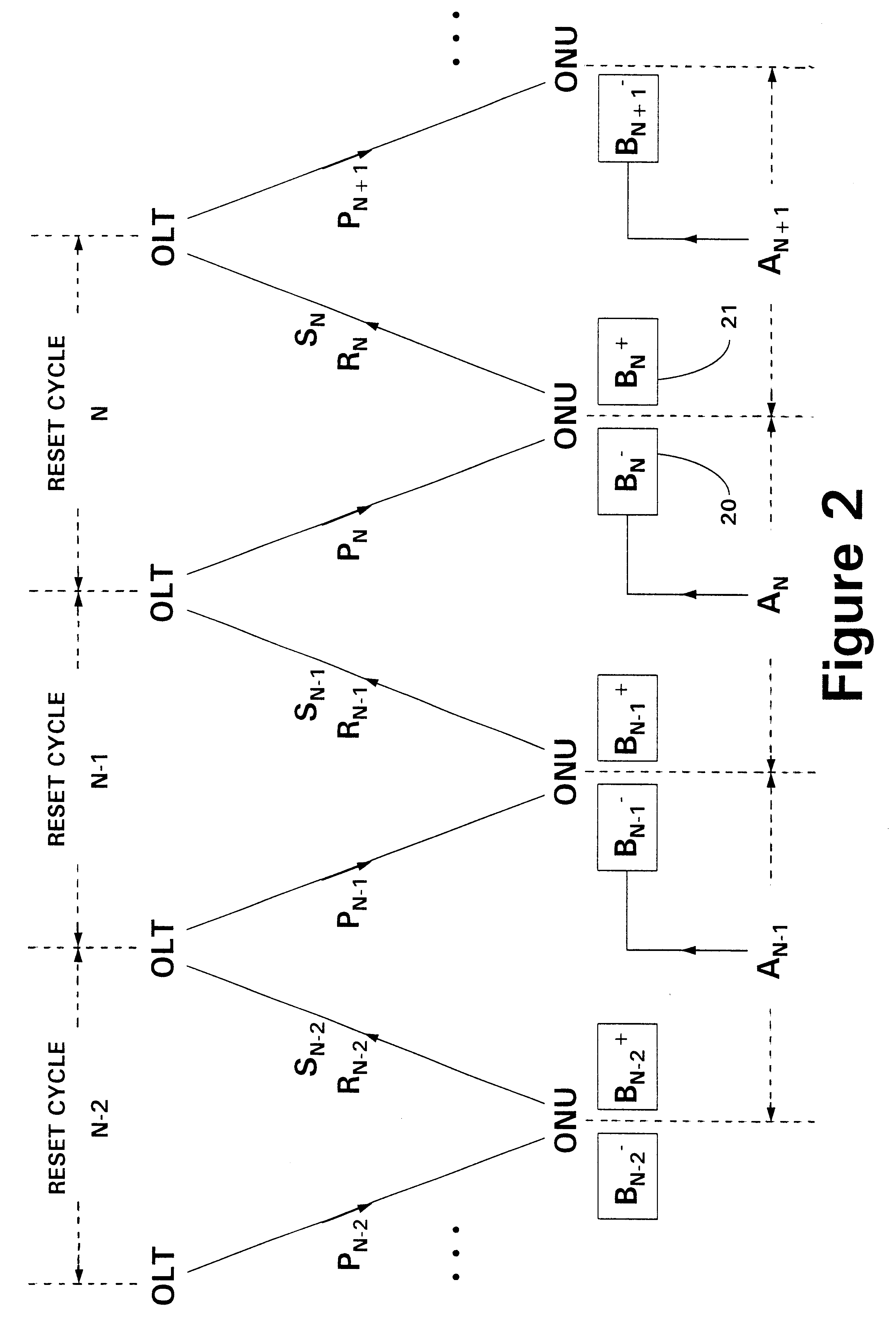
FIG. 2 shows the parameters of a polling sequence used in preferred embodiments of the invention;

Referring to FIG. 1, a section of a typical known local access PON having a "star" configuration is shown, including an optical waveguide 1, an optical line termination unit (OLT) 2 connected to the "head-end" of the optical waveguide 1, a number of optical network units (ONUs) 3, each connected to the end of a branch--a "user end"--split from the waveguide 1 by one or more passive optical splitters 4, two levels of split being shown in FIG. 1. ONUs 3 provide an interface to the PON for user equipment 5, connected to ONUs 3 typically by non-optical connection means. The OLT 2 includes an optical transmitter 6 and an optical receiver 7, each connected to the optical waveguide 1. Th...


PUM


Abstract

A communications network includes an optical waveguide to which is connected a head-end station and at lest one optical network unit (ONU). An ONU provides an interface to the communications system for connected user equipment. Data received by an ONU from connected user equipment are stored in a buffer prior to transmission to the head-end station. The head-end station is arranged to implement, in conjunction with the ONUs a demand-assignment protocol for the transfer of data upstream from the ONUs to the head-end station according to which an ONU demands upstream capacity based upon a prediction of its future capacity requirements, calculated using at least one record of earlier granted capacity by the head-end station and at least one measurement of a quantity of data awaiting transmission to the head-end station in the buffer of the ONU.

Description

1. Field of the InventionThis invention relates to communications networks, and has particular utility in relation to Passive Optical Networks (PONs).2. Related ArtPONs are commonly used in point to multi-point communications applications, for example in a broadband local access optical network providing broadband services to residential and small business users. In a PON providing a point to multi-point local access optical network, a so called optical line termination unit (OLT) is provided, connected to the "head end" of the PON and located, typically, in a local telephone exchange. The OLT controls access to the shared capacity of the PON and interconnects the PON with a wider telecommunications network. So called optical network units (ONUs) are connected to the "user ends" of the PON, typically up to 10 km downstream from the OLT, to provide points of connection to users, to multiplex services and to communicate over the PON with the OLT.Conventionally, data are passed over th...

Claims


Application Information

Patent Timeline
Patent Type & Authority Patents(United States)
IPC IPC(8): H04B10/207H04L12/403H04B10/272
CPCH04B10/272
Inventor QUAYLE, JOHN ALAN
Owner INTPROP ASSET MANAGEMENT LLC
Learn More