

Brush-seal designs for elastic fluid turbines
a technology of elastic fluid turbines and brush seals, which is applied in the direction of liquid fuel engines, machines/engines, mechanical equipment, etc., can solve the problems of reducing the performance of the turbine, degrading the tip seal, and damage thereto, so as to avoid shortcomings and drawbacks
- Summary
- Abstract
- Description
- Claims
- Application Information
AI Technical Summary
Benefits of technology
Problems solved by technology
Method used
Image

Examples
Embodiment Construction
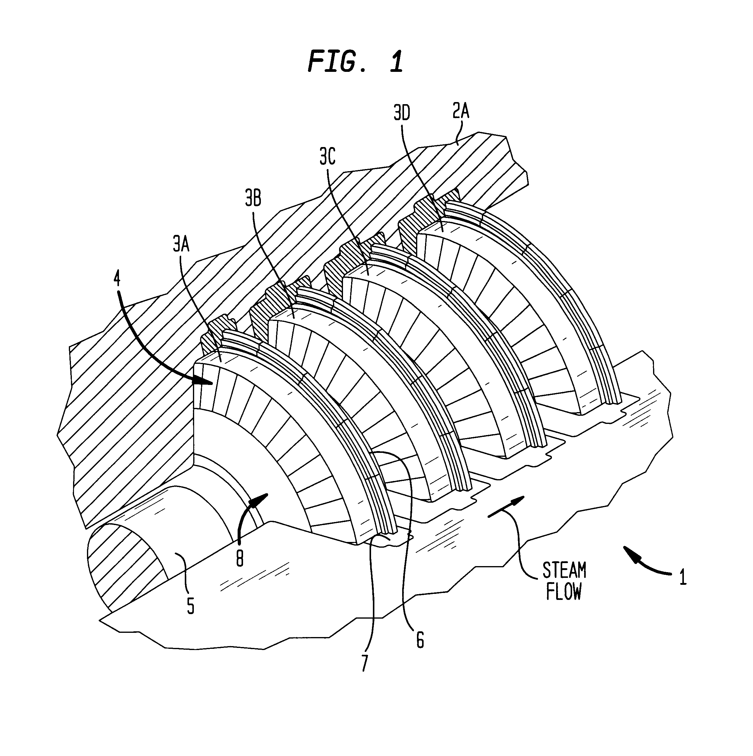
In general, the axial flow steam turbine 1 of the present invention generally comprises a number of turbine sections which are conventionally classified by operating pressure. Along each turbine section, a number of stages are encased within outer turbine casting 2 as shown in FIG. 1. In the illustrative embodiment, these turbine stages are identified by 3A, 3B, 3C, and 3D in FIG. 1. In general, however, the number of stages will vary from embodiment to embodiment of the present invention. Hereinafter, like reference numerals are used to indicate like structures.
Referring to FIGS. 1 through 3, the major components of the turbine system hereof will be described.
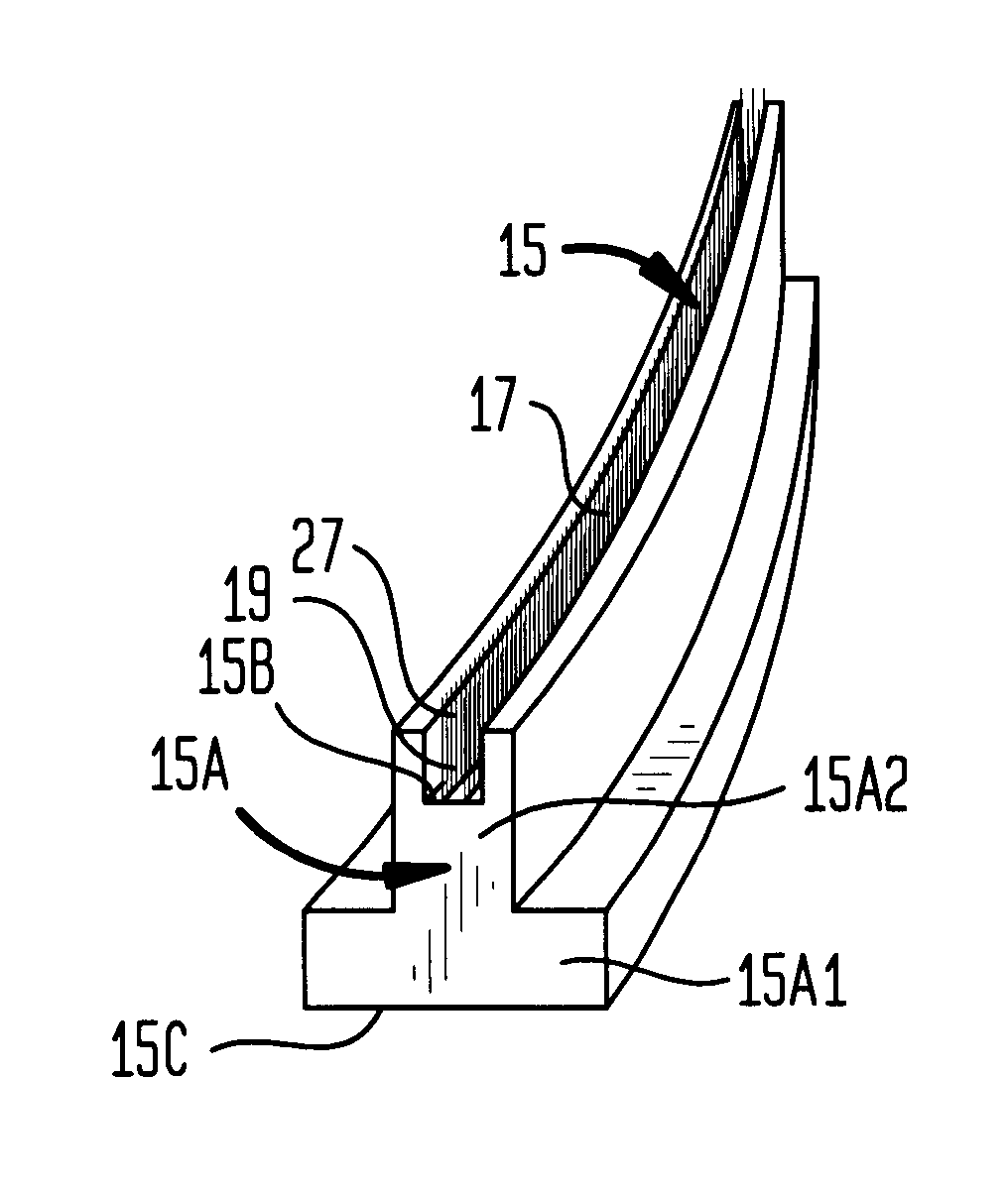
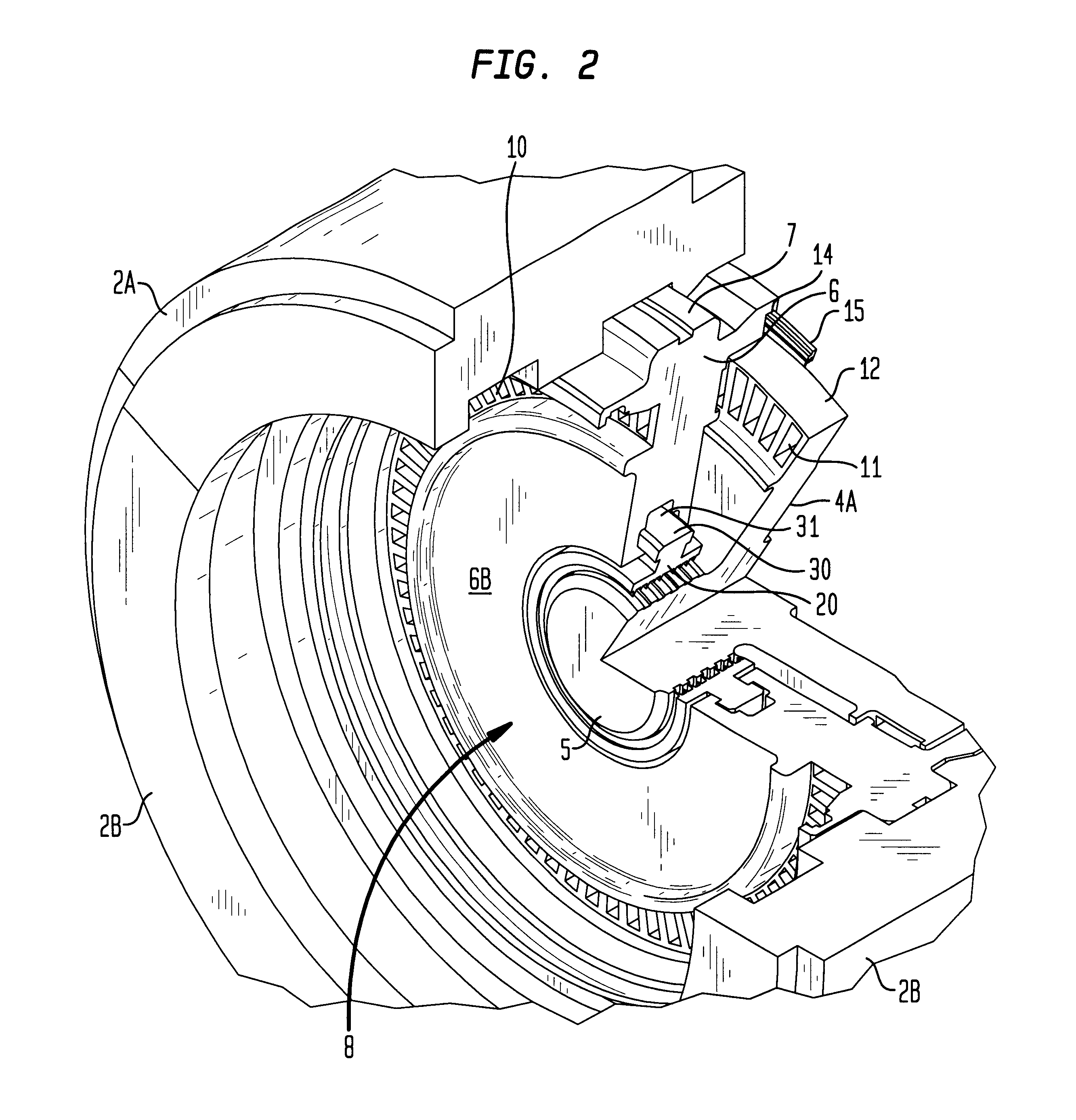
As shown in FIG. 1, each stage of the turbine has a turbine rotor 4 fixedly mounted to the rotor (i.e., turbine) shaft 5, and an associated turbine diaphragm 6 stationary mounted in a joint 7 in the outer turbine casing 2. The position of each turbine rotor is located slightly downstream from its associated diaphragm 6. As sho...
PUM
 Abstract
Description
Claims
Application Information