Foldable member

Inactive Publication Date: 2001-11-27
FOSTER-MILLER
View PDF40 Cites 64 Cited by
  • Summary
  • Abstract
  • Description
  • Claims
  • Application Information

AI Technical Summary

Benefits of technology

This invention results from the realization that a lighter and more dimensionally stable, foldable member can be constructed by cutting or forming longitudinal slots in a tube around the perimeter thereof at a location where the member is designed to bend thereby forming separated, longitudinal strips of tube material at that location which easily buckle allowing the mem

Problems solved by technology

Existing deployable structure joints have several limitations that either completely prevent them from being used in high precision deployable instruments or require complex analysis and additional launch mass to provide deployment actuation and post deployment locking.
These joints have been shown to be unstable at the micron level, causing the structure to "micro-lurch" or change shape and thus move the instrument's optics far out of alignment.
Unfortunately, these high levels of preload introduce correspondingly high levels of friction both during the deployment and after deployment has been completed.
Friction mechanisms are nonlinear and thus are more difficult to control and less predictable.
Other hinge designs such as latch and actuator type systems suffer from the same disadvantages.
All of these mechanisms add to the mass, expense and complexity of the struct

Method used


Image

  • Foldable member
  • Foldable member
  • Foldable member

Examples


Embodiment Construction

Other objects, features and advantages will occur to those skilled in the art from the following description of a preferred embodiment and the accompanying drawings, in which:

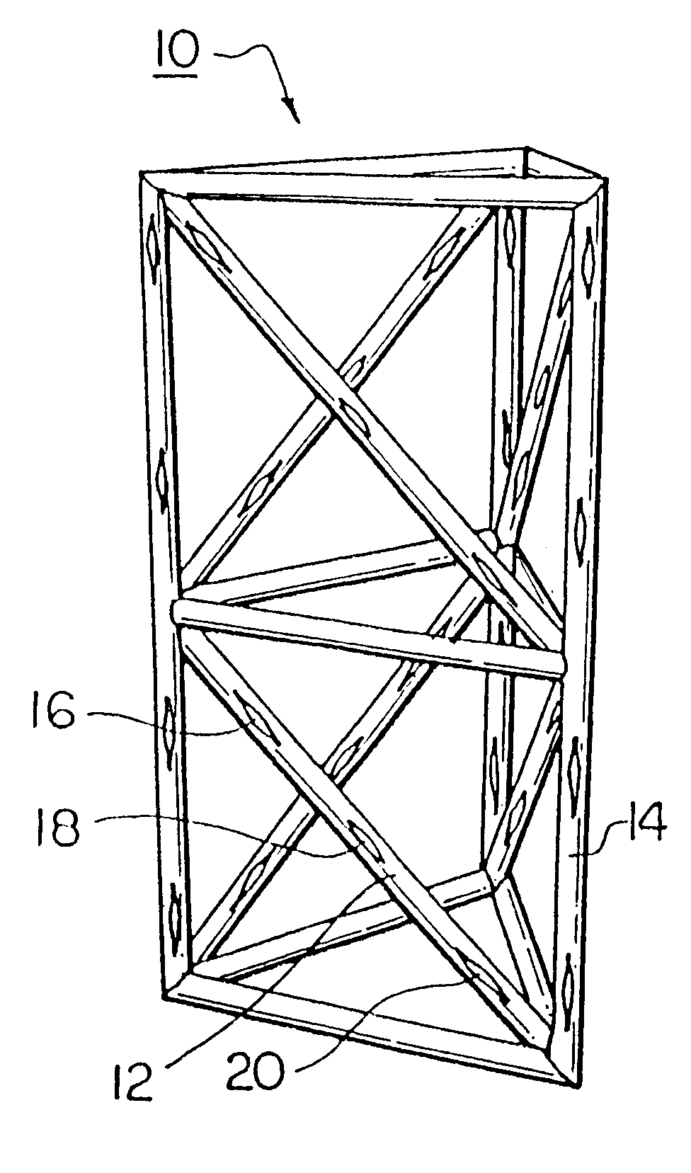
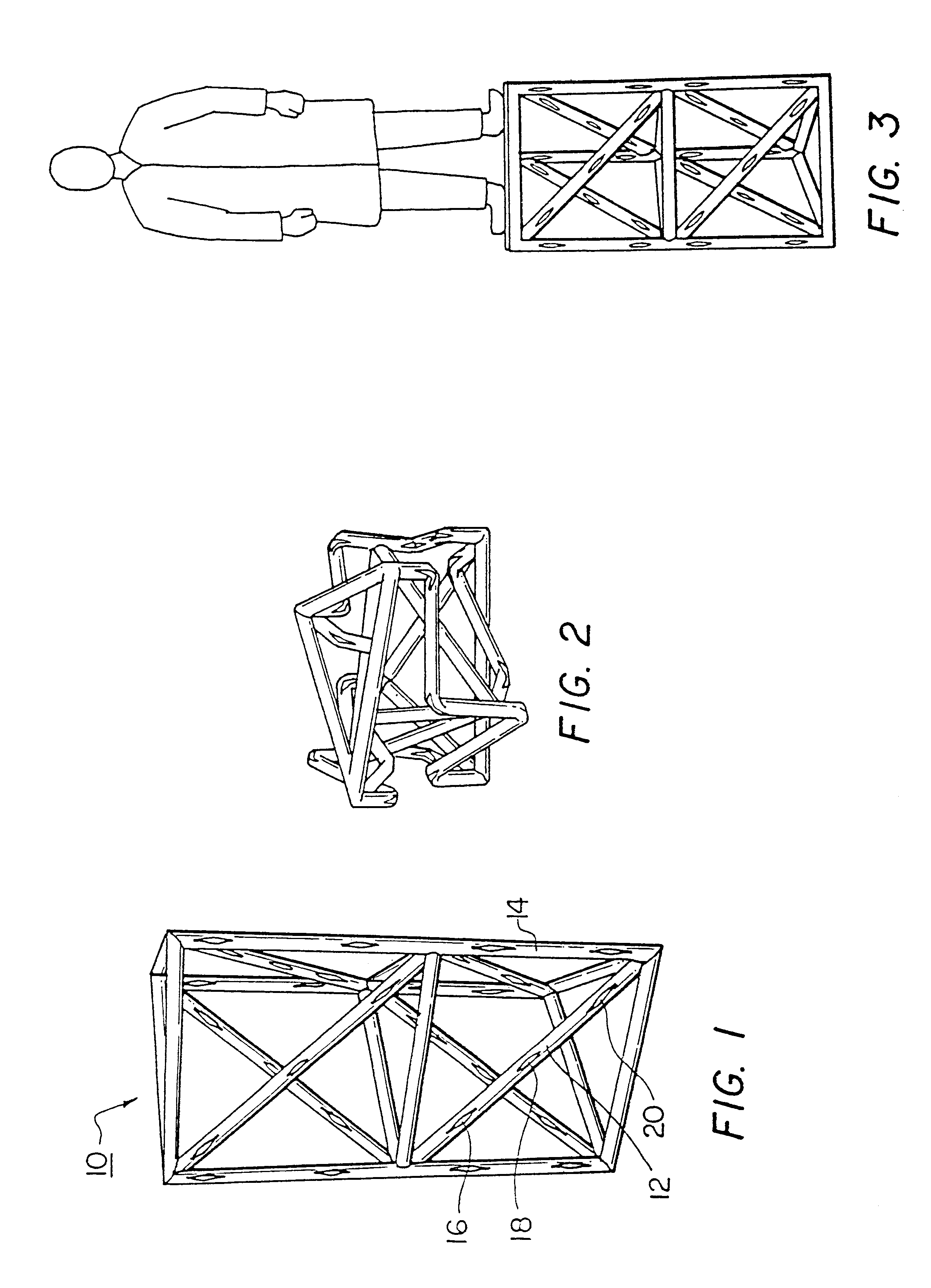
FIG. 1 is a perspective view of a structure made of a number of foldable members in accordance with the subject invention;

FIG. 2 is a schematic view of the structure shown in FIG. 1 in a collapsed state;

FIG. 3 is a perspective view of the structure of FIG. 2 after it expands from the collapsed condition;

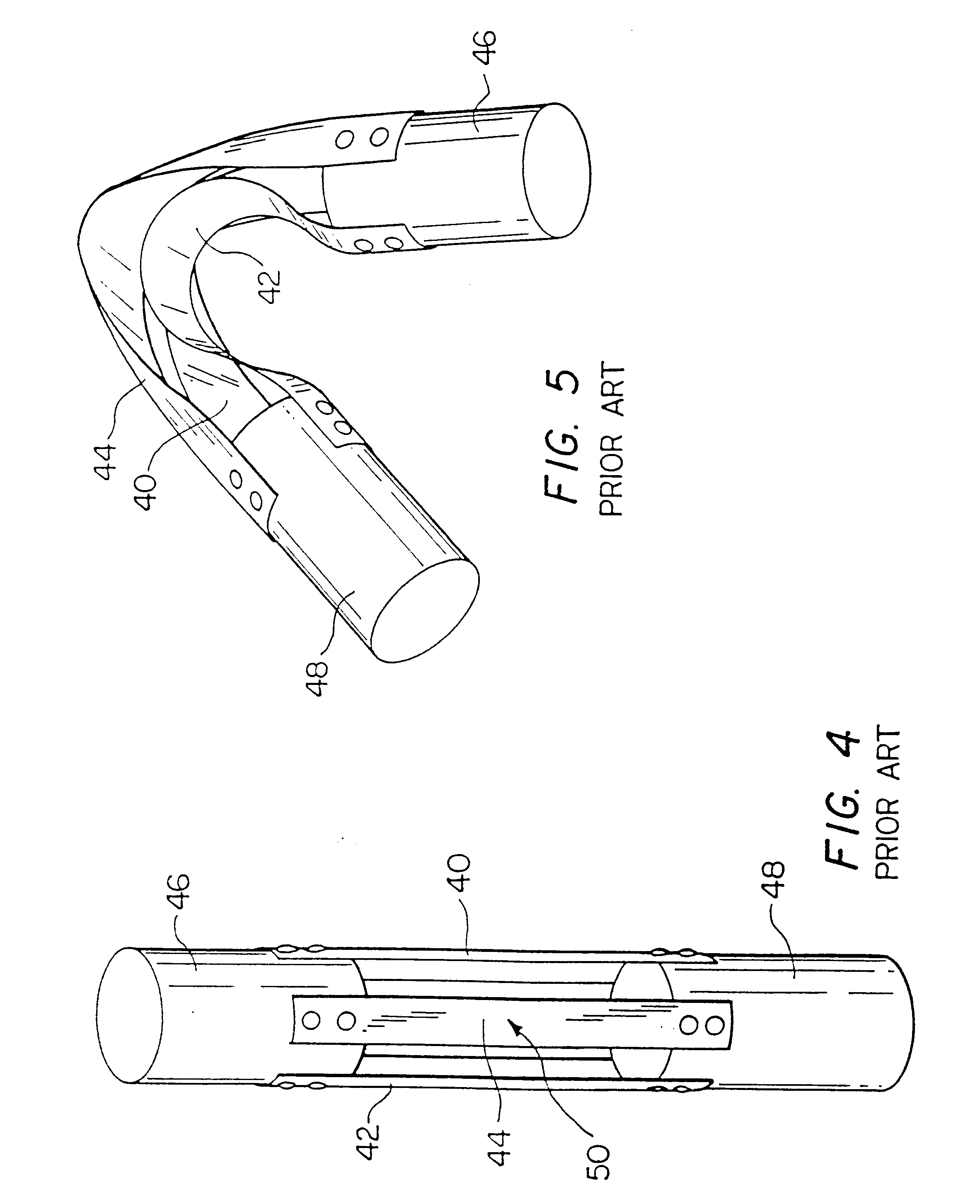
FIG. 4 is a front elevational view of a prior art foldable device;

FIG. 5 is a view of the prior art device shown in FIG. 4 in the folded position;

FIG. 6 is a side elevational view of the foldable member of the subject invention;

FIG. 7 is a front elevational view of the foldable member shown in FIG. 6;

FIG. 8 is a schematic view of the foldable member shown in FIGS. 6 and 7 in a folded position;

FIG. 9 is a front elevational view of another embodiment of the foldable member of this invention;

FIG. 10 is a side eleva...


PUM

PropertyMeasurementUnit
Lengthaaaaaaaaaa
Forceaaaaaaaaaa
Structureaaaaaaaaaa

Abstract

A foldable member in the shape of a tube with at least one predetermined hinge area along the length of the tube, and a plurality of opposing elongated slots in the tube at the hinge area thereof forming separated longitudinal strips of tube material between the slots which fold when subjected to localized buckling forces. A collapsible structure constructed of such foldable members.

Description

RELATED PATENT APPLICATIONThis application is a divisional application of a patent application entitled "Foldable Member" by the same inventor as the subject application filed on Nov. 9, 1999.This invention relates to a foldable boom, truss, or longeron member, collapsible trusses and other similar structures made of such members.BACKGROUND OF INVENTIONKey optical components of large aperture, space based optical instruments may be deployed on orbit to provide an aperture large enough to increase the resolution and optical performance by several orders of magnitude. The performance of such instruments depends on maintaining the precision and stability of the deployed structural geometry to within nanometers of an ideal shape. Nonlinear contact mechanics and freedom in the components of deployed structures mean that deployed instruments will have the capacity to change shape at the micron and nanometer level of resolution. Eliminating such nonlinearities as load path friction and fre...

Claims


Application Information

Patent Timeline
IPC IPC(8): B64G9/00B64G1/22E04B1/344B64G99/00
CPCB64G1/222B64G9/00E04B1/3441Y10S16/13Y10T403/5766Y10T403/34Y10T403/5786Y10T16/525Y10T403/5761B64G99/00
Inventor WARREN, PETER A.
Owner FOSTER-MILLER
Why Eureka
Try Eureka