Dual-protocol locomotive control system and method

a control system and dual-protocol technology, applied in the field of intratrain communication, can solve the problems of increasing the time and distance required for the train, increasing the possibility of a derailment, and consequently losing life and property

Inactive Publication Date: 2001-11-27
WESTINGHOUSE AIR BRAKE TECH CORP
View PDF5 Cites 136 Cited by
  • Summary
  • Abstract
  • Description
  • Claims
  • Application Information

AI Technical Summary

Benefits of technology

It is second objective of the present invention to achieve the first objective by automatically detecting the type of head unit and remote unit on the train. including the protocol each operates under, and then automatically performing the protocol and arming conversions required to establish a reliable communications link between the lead unit and remote unit, thereby increasing operational efficiency in a manner which is virtually transparent to the operator.
It is another objective of the present invention to achieve the foregoing objectives without requiring any changes to the software which controls the operation of the head unit, e.g., IFC or ICE.
It is another object of the present invention to provide a system and method of the aforementioned type which increases safety by reducing the possibility that the system will be improperly configured because of human error, thereby ensuring that the train will at all times be operational for an emergency brake application.
These and other objectives of the present invention are achieved by providing a system and method for establishing a communication link between a first unit and a second unit of a train. In accordance with this method, a cab control unit in a lead locomotive is provided operating in accordance with a first protocol, and an end-of-train unit is attached to a trailing car of the train, which end-of-train unit operates in accordance with a second protocol. The method then automatically detects in a locomotive control unit that the cab control unit is a type operating in the first protocol. This step is followed by automatically detecting in the locomotive control unit that the end-of-train unit is a type operating in the second protocol. Protocol conversions are then automatically performed in order to communicate information between the end-of-train unit and the cab control unit. Preferably, one of the protocols is the AAR protocol: however, the method of the present invention may be applied to perform the data field conversions required to convert between any two protocols known. The end-of-train unit may be automatically detected according to a polling algorithm and then determining which frequency band a return message is received in. The cab control unit is automatically detected based on the arming procedures that are implemented. The resulting system and method thus advantageously allows different devices to communicate with one another on a single train, thereby increasing operational efficiency and convenience throughout the railroad industry.

Problems solved by technology

These one-way units have proven inadequate in a number of ways.
This sequential application of the brakes increases the time and distance required for the train to come to a complete stop, especially for long train consists.
Furthermore, if a blockage or restriction were present in the brake pipe, the brakes beyond the restriction may not engage, increasing the possibility of a derailment and consequently loss of life and property.
This presents compatibility problems, since unless some protocol conversion takes place the LCU and EOT will not be able to communicate with one another.
This LCU, however, has proven inadequate in at least three ways.
First, this system performs protocol conversions solely as the result of manual operations.
Second, this manual system requires the IFC software to be either re-programmed or changed to handle differences in the arming procedure.
If these software changes are not made, IFC operation would be inconsistent with the EOT operation, which could potentially prevent the system from arming properly.
Third, this manual system is highly susceptible to malfunctioning because of operator error.
For example, such a system is potentially dangerous because if the switch on the LCU panel were changed to the wrong setting no communications would take place between the LCU and EOT.

Method used


Image

  • Dual-protocol locomotive control system and method
  • Dual-protocol locomotive control system and method
  • Dual-protocol locomotive control system and method

Examples


Embodiment Construction

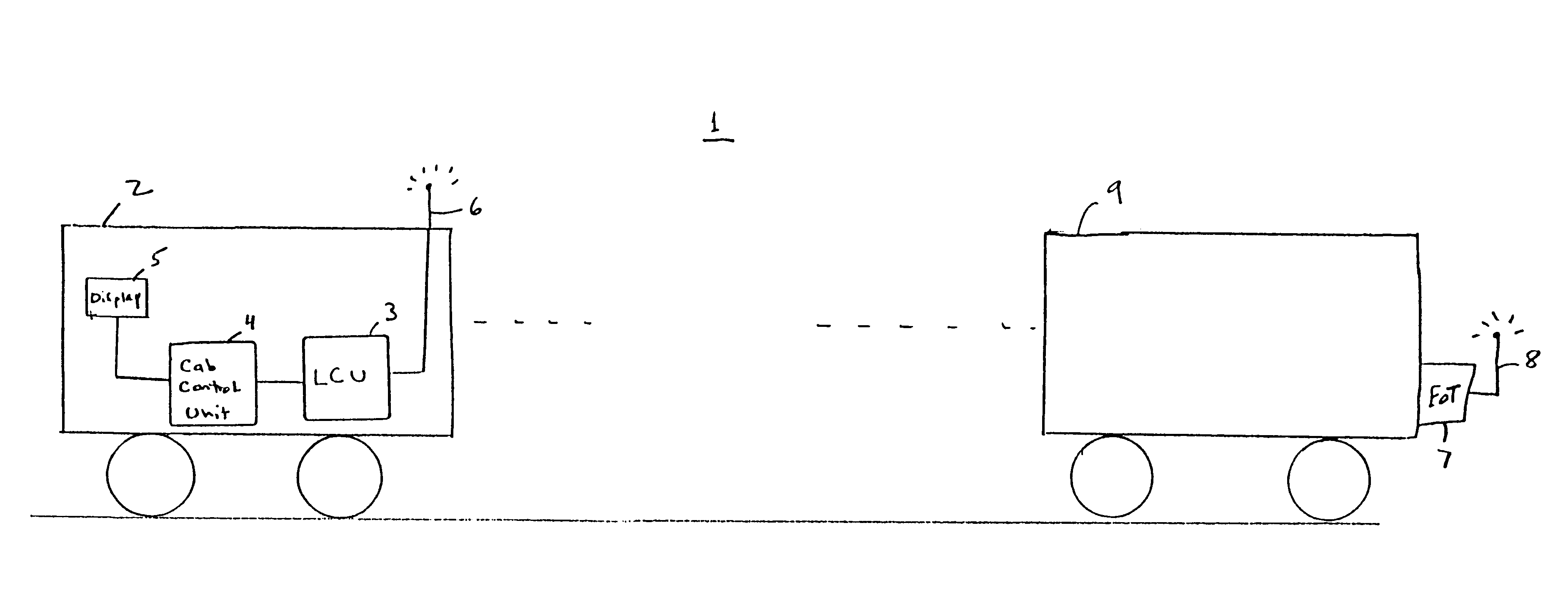
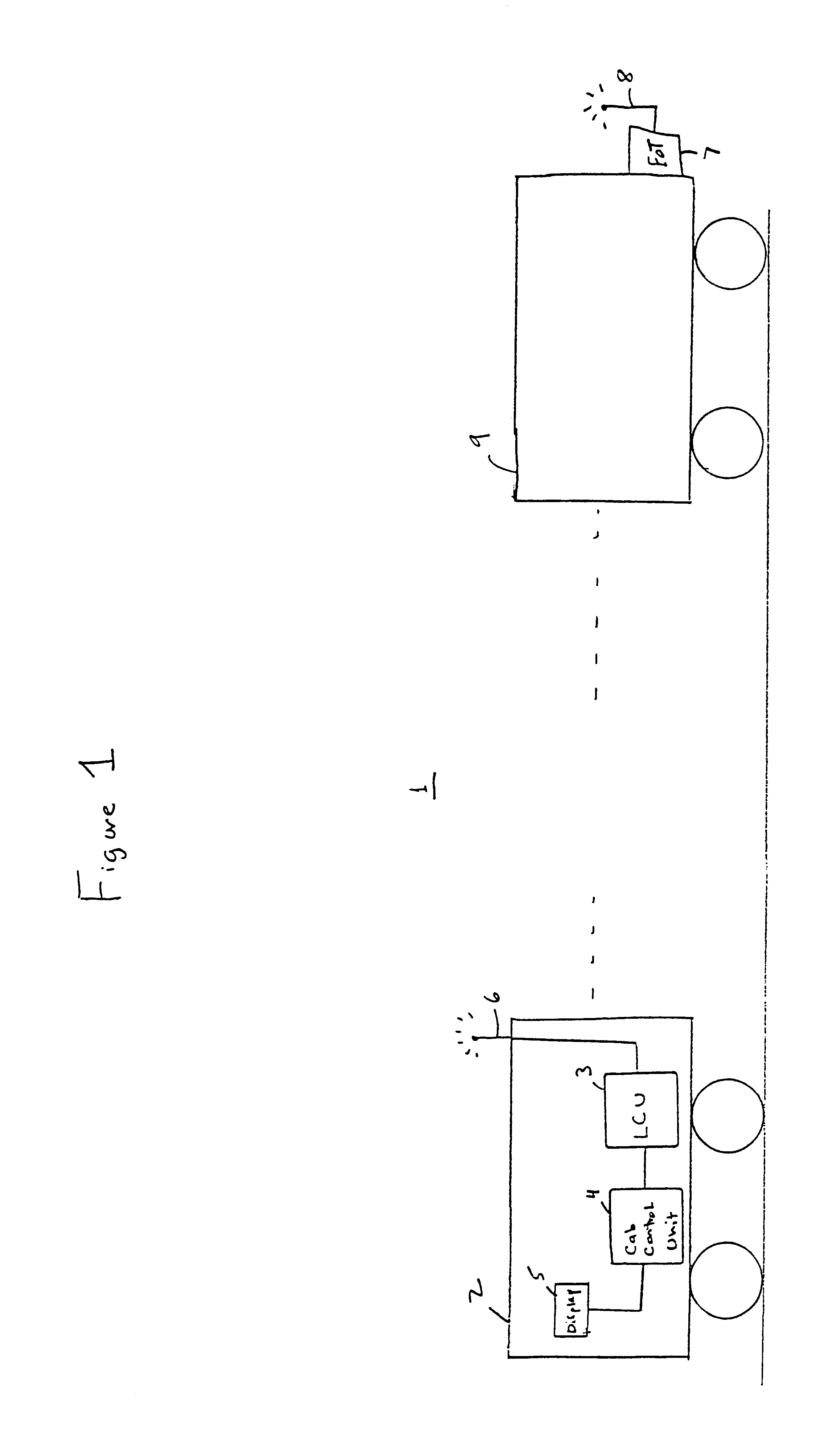
Referring now to the drawings and more particularly to FIG. 1, an intra-train communications system 1 includes, at a leading end, a locomotive 2 equipped with a locomotive control unit 3 in accordance with the present invention, an integrated cab control unit 4, a display 5, and an antenna 6. Integrated cab control unit 4 may include a computer which integrates all of the electrical systems in the locomotive. Computers of this type include the Integrated Function Computer (IFC) manufactured by General Electric and the Rockwell (now Westinghouse Air Brake Company) integrated cab electronics (ICE) unit. Those skilled in the art can appreciate, however, that unit 4 may be any cab control unit conventionally known. Further, while the locomotive control unit 3 is shown as mounted on the lead locomotive, an optional configuration would place this unit on one or more trailing locomotive, if the train is so arranged.

At a trailing end, system 1 includes a unit 7 and an antenna 8 attached to ...


PUM


Abstract

An intra-train communication system includes a locomotive control unit (LCU) establishes a communications link between a lead unit and a remote unit which operate using different protocols and / or in different frequency bands. To accomplish this objective, the LCU automatically detects the type of lead unit and remote unit installed on the train. If the types are not the same, the LCU resolves any serial link protocol and arming differences that might exist in a manner virtually transparent to train operators. As a result, data is communicated between the lead and remote units in a way which requires less operator intervention and no software changes to the control computer of the head unit.

Description

1. Field of the InventionThe present invention generally relates to intra-train communications, and more particularly to a system and method for communicating data between a head unit in a lead locomotive and one or more trailing units which operate in accordance with different data protocols.2. Background DescriptionWireless communications systems have been developed for improving the command and control response time of a train. These systems typically include an end-of-train (EOT) unit containing a telemetry transmitter attached to the last car of a train in the place of a caboose, and a computer commonly referred to as a locomotive control unit (LCU) or head-of-train unit installed in the lead locomotive.EOT units perform three principal functions. First, they monitor various operating conditions of the train including air pressure in the brake line, battery condition, marker light condition, motion, and emergency valve status. EOT units also perform marker light operations and ...

Claims


Application Information

Patent Timeline
Patent Type & Authority Patents(United States)
IPC IPC(8): B61L15/00
CPCB61L15/0027B61L15/0036B61L15/0054B61L25/023
Inventor COLBERT, MICHAEL A.PASCAL, GILWRIGHT, CLIVE B.
Owner WESTINGHOUSE AIR BRAKE TECH CORP
Why Eureka
Try Eureka