
Arm member

a technology of arm member and arm member, which is applied in the direction of non-disconnectible pipe-joints, couplings, manufacturing tools, etc., can solve the problems of easy-to-broke arm member 51, cracks at or approximating the joined portion w, etc., and achieves the effect of light weigh

Inactive Publication Date: 2001-12-04
SHOWA DENKO KK +1
View PDF10 Cites 28 Cited by
  • Summary
  • Abstract
  • Description
  • Claims
  • Application Information

AI Technical Summary

Benefits of technology

An object of the present invention is to provide an arm member which is light in weight and can prevent cracks from causing at or approximate to the joined portion, even though the main body of the arm member used for a suspension arm or an engine mount is made of a pipe member.
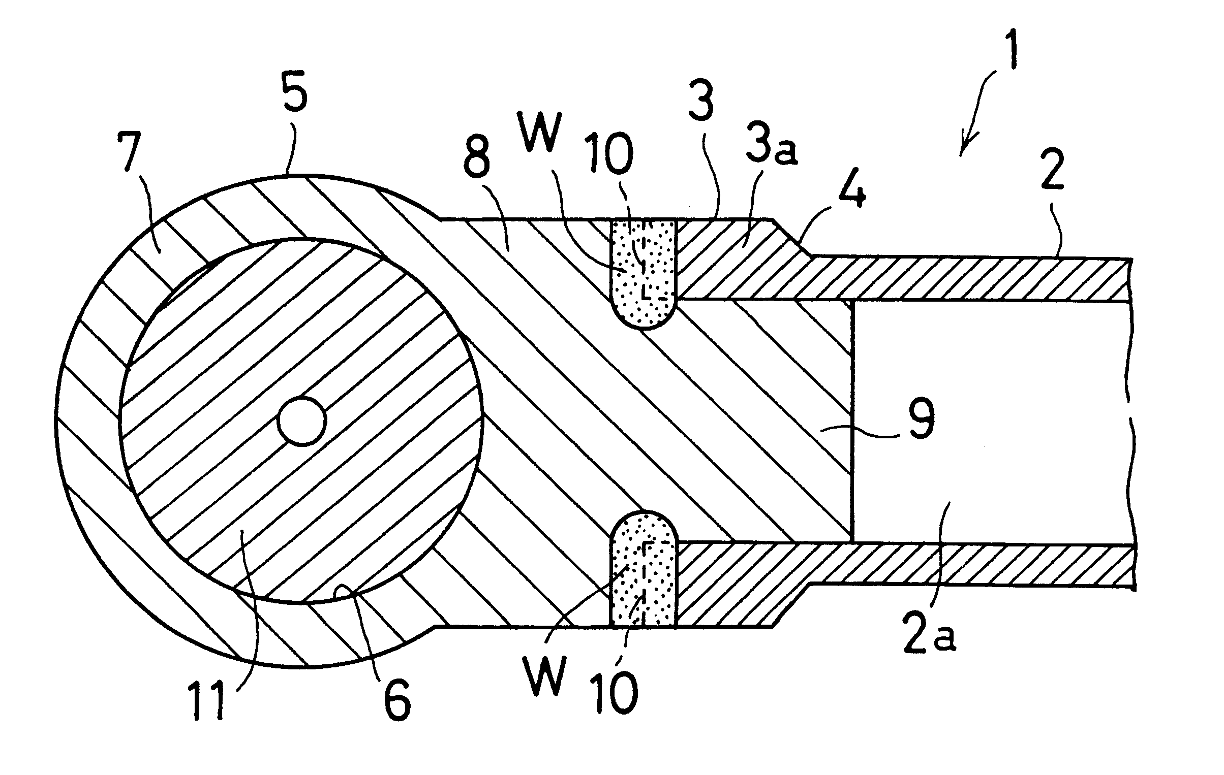
In this arm member, since the main body is made of a pipe member, the result is the arm member which is light in weight. Also, since the peripheral wall of the end portion of the main body is formed to have a thickness thicker than that of the other portion of the main body, the mechanical strength of the end portion of the main body is enhanced. Therefore, fracture or breakage at or approximate to the joined portion due to a tensile load or the like imparted thereto can be prevented from occurring. Furthermore, since the peripheral wall of the end portion of the main body is formed to have a thickness thicker than that of the other portion of the main body, thermal fatigue hardly occurs by the joining heat. This also can prevent the end portion of the main body from causing cracks at or approximate to the joined portion. As a result, even though the main body is made of a pipe member, the coupling member is firmly coupled to the main body. In other words, the arm member light in weight and high in joint strength can be provided.
In the aforementioned arm member, it is preferable that the peripheral wall of the end portion of the main body is radially outwardly increased in thickness. This structure simplifies the process of making the thick peripheral wall at the end portion of the main body.
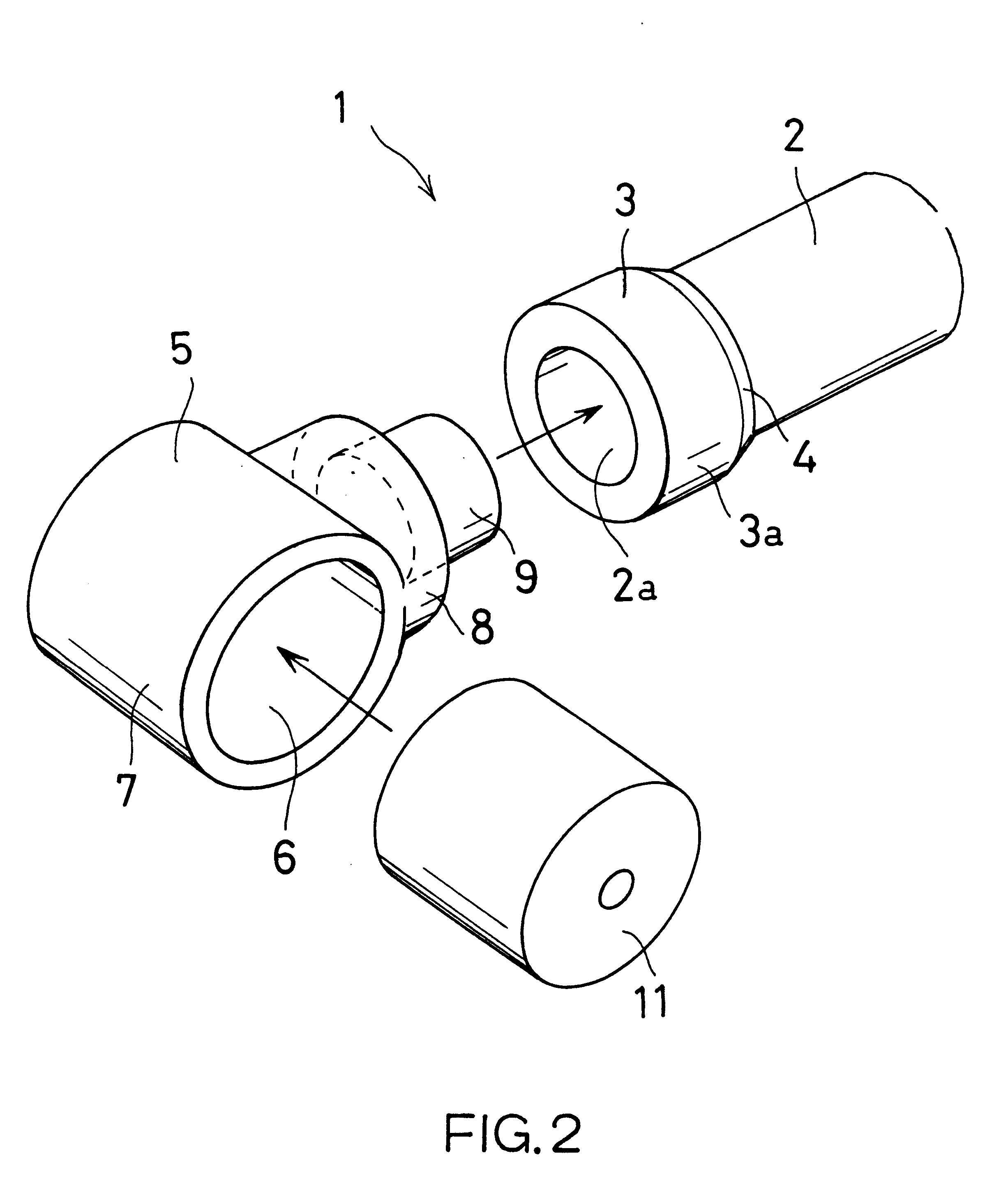
It is preferable that a protruded portion integrally formed on the connecting portion is fitted in an opening of the end portion of the main body. This further enhances the mechanical strength of the peripheral wall of the end portion of the main body since the protruded portion fitted in the opening of the end portion of the main body reinforces the peripheral wall of the end portion of the main body from inside of the pipe member.
In the aforementioned arm member, it is preferable that the pipe member and the coupling member are made of metal and the abutted portion is joined, or welded by a friction agitation joining method. The friction agitation joining method is one of the solid-phase joining or welding methods and generates joining heat less than that in a fusion welding method, which causes less thermal fatigue at the joined portion. Accordingly, the aforementioned arm member has almost no thermal fatigue at the joined portion, whereby cracks due to thermal fatigue at and approximate to the joined portion can be surely prevented from causing. Further, the friction agitation joining method has advantages in that it is possible to firmly join different kinds of metals. Accordingly, in the aforementioned arm member, even though the main body and the coupling member are made of different kinds of metals, the main body and the coupling member can be joined firmly.
According to this aspect of the present invention, since both of the main body and the coupling member are made of aluminum, the arm member becomes further light in weight. Furthermore, since the abutted portion is joined by the friction agitation joining method, cracks due to thermal fatigue at and approximate to the abutted portion can be surely prevented.

Problems solved by technology

However, a conventional arm member, in which the main body and the coupling member are joined by a joining method such as a fusion welding (a MIG welding, a TIG welding, a laser welding, or the like) or a solid-phase welding method (a friction agitation joining method), may cause cracks at or approximate to the joined portion W' when a tensile load is imparted thereto.
The thermal fatigue may cause cracks at or approximate to the joined portion W', resulting in an easy-broken arm member 51.

Method used


Image

  • Arm member
  • Arm member
  • Arm member

Examples


first embodiment

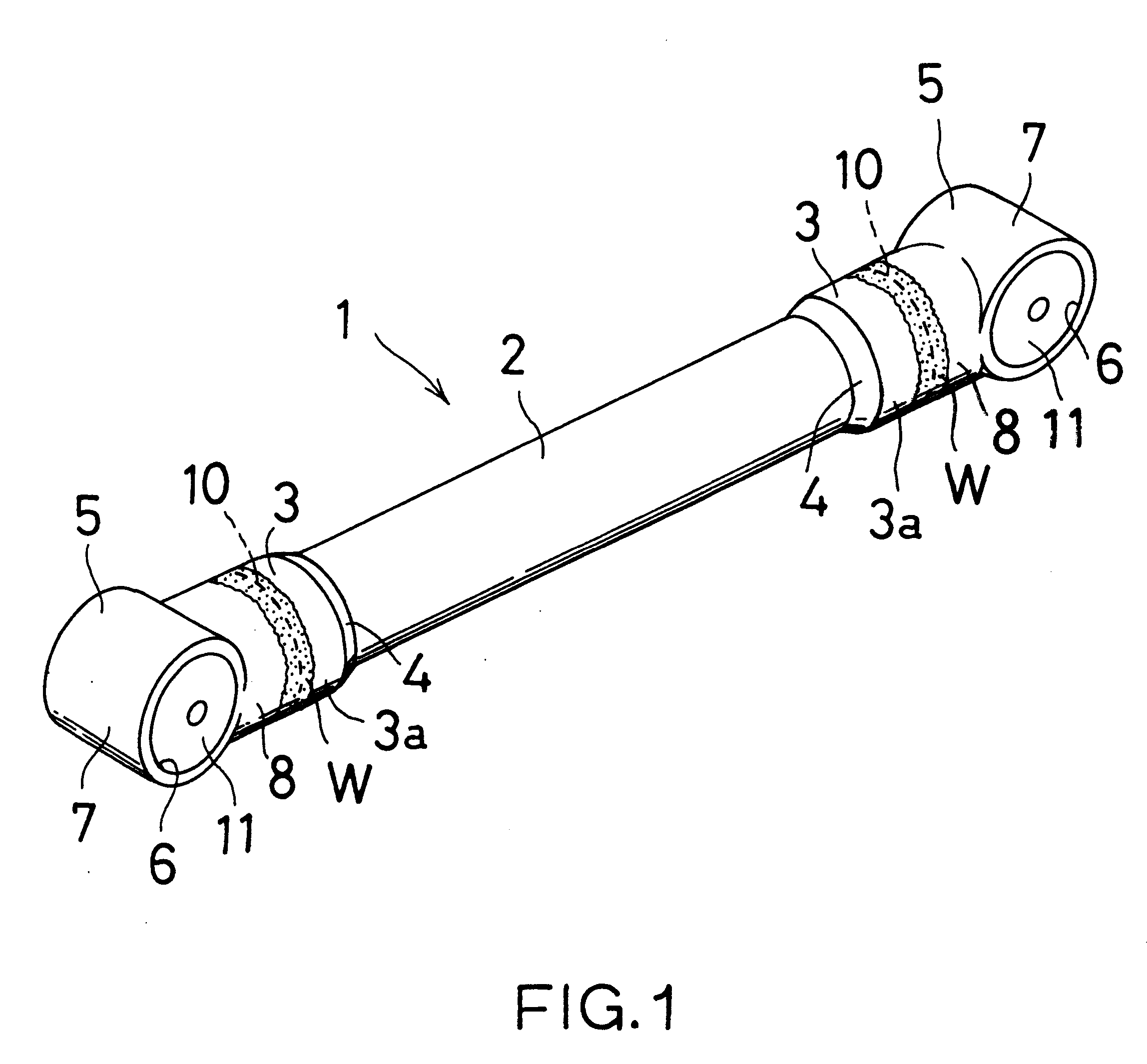
FIGS. 1 to 4 illustrates an arm member 1 according to the present invention. As shown in FIG. 1, the arm member 1 comprises a main body 2 made of an aluminum cylindrical pipe having a predetermined length and a pair of coupling members 5 and 5 made of aluminum die casting and connected to the longitudinal opposite end portions 3, 3 of the main body 2. As shown in FIG. 2, the peripheral wall of the end portion 3 of the main body 2 is made to have a thick peripheral wall 3a radially outwardly increased in thickness so as to have a thickness thicker than that of the other peripheral portion of the main body 2. Furthermore, in the main body 2, the outer surface of the peripheral wall of the end portion 3 is connected to the outer surface of the other peripheral wall of the other portion of the main body 2 via a tapered surface 4. This eases the stress concentration to be imparted to the stepped portion between the end portion 3 and the other portion of the main body 2.

Thickening the per...


PUM

PropertyMeasurementUnit
Thicknessaaaaaaaaaa
Metallic bondaaaaaaaaaa
Elasticityaaaaaaaaaa

Abstract

An arm member is used as, for example, a suspension arm of an automobile. The arm member comprises a main body made of a pipe member and a coupling member having a connecting portion. The pipe member is made of aluminum or its alloy. The coupling member is made of aluminum and includes a bushing mounting portion for mounting a vibroisolating bushing. The thickness of the peripheral wall of the end portion of the main body is increased in thickness to have a thickness thicker than that of the other portion of the main body. The connecting portion is abutted to the peripheral wall of the end portion to form an abutted portion, and connected thereto at the abutted portion. Thus, the coupling member is coupled to the main body.

Description

BACKGROUND OF THE INVENTION1. Field of the InventionThe present invention relates to an arm member for use as, for example, an automobile suspension arm or an engine mount, and more particularly, to an arm member which is to be coupled with the other members and includes a coupling member with a bushing mounting portion, a yoke portion, a ball joint mounting portion, or the like.The term "aluminum" used in this specification denotes aluminum and its alloys.2. Description of the Related ArtFIGS. 8A and 8B illustrates an arm member 51 for use as an automobile suspension arm such as an upper arm, a lower arm, a trailing arm and a torsion arm.The arm member 51 comprises a main body 52 and a pair of metallic coupling members 55 each connected to the respective end portion 53 of the main body 52. The main body 52 is made of a metallic cylindrical pipe having a predetermined length in order to lighten the arm member 51.The coupling member 55 comprises a cylindrical bushing mounting portion...

Claims


Application Information

Patent Timeline
IPC IPC(8): B60G7/00B23K20/12F16B11/00F16C7/02
CPCB60G7/001F16C7/02B23K2201/06B60G2206/11Y10T403/477B60G2206/8201Y10T403/64B60G2206/7102B23K2101/06F16C2326/05F16B2200/50
Inventor KATO, RENTAROOGAWA, YUICHIUCHINO, KOJITOCHIGI, MASAHARUKAWATA, NAOYUKIHASHIMOTO, TAKENORI
Owner SHOWA DENKO KK
Learn More