Method of braking a vector controlled induction machine, control device for carrying out the method and storage medium

a vector controlled induction machine and control device technology, applied in the direction of electronic commutation motor control, control system, electric generator control, etc., can solve the problems of increasing the cost of ac drive, reducing reliability, and the diode bridge not being able to re-regenerate power to the ac supply, so as to achieve maximum braking ability, improve field oriented control, and high dynamic performance

Inactive Publication Date: 2001-12-04
WEG AUTOMACAO
View PDF11 Cites 37 Cited by
  • Summary
  • Abstract
  • Description
  • Claims
  • Application Information

AI Technical Summary

Benefits of technology

To ensure the required dynamic performance, the present invention is based on and improves the field oriented control. Thus, the method and device according to the invention are applicable to variable speed AC FO control drives and achieve both at the same time: a maximum braking ability and a very high dynamic performance.

Problems solved by technology

However, a diode bridge is not capable of regenerating power to the AC supply.
This makes extra power electronics and control electronics necessary, and thus increases the cost of the AC drive, and reduces its reliability.
A portion of it is lost as windage and friction losses, which losses depend on the rotor speed.
Friction and windage losses are also very small if forced ventilation is assumed.
Although the stator current has a maximum value in this case, the resulting braking power is very small.
Only the energy dissipated in the rotor resistances is supplied by the shaft power, and hence the braking power is low.
This means that the capability of the motor to dissipate the braking power is badly exploited.
Apart from the poor ability to develop braking torque, the method of DC braking exhibits also a poor dynamic performance, since the flux can not be abruptly changed.
This means that the motor dissipates only 30% of its rated losses at field oriented braking.
Moreover, all losses must be supplied by the shaft power, not by the inverter.

Method used


Image

  • Method of braking a vector controlled induction machine, control device for carrying out the method and storage medium
  • Method of braking a vector controlled induction machine, control device for carrying out the method and storage medium
  • Method of braking a vector controlled induction machine, control device for carrying out the method and storage medium

Examples


Embodiment Construction

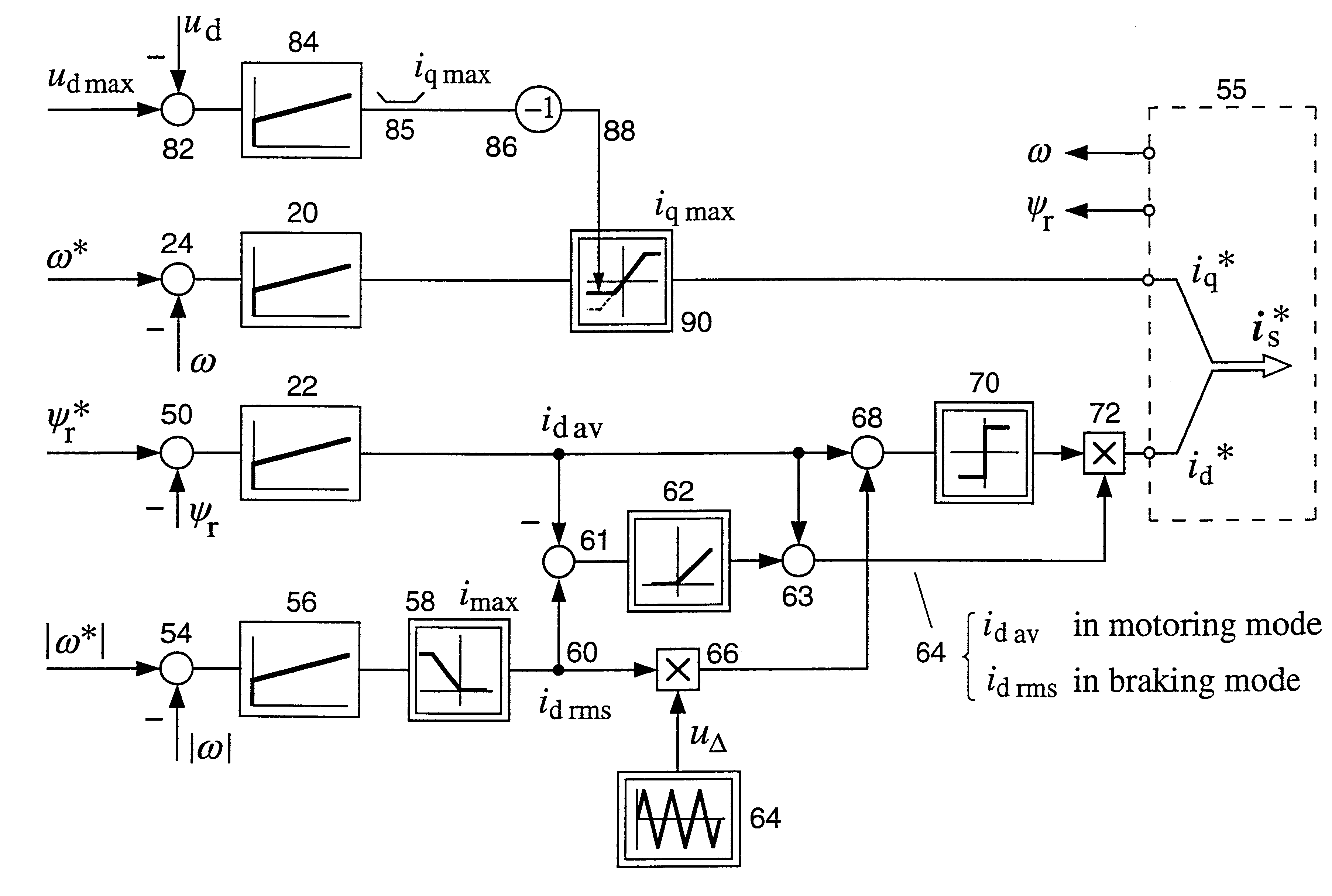
To ensure the required dynamic performance, the machine is operated at field oriented control. The electromagnetic torque

T.sub.e =k.sub.r.psi..sub.r i.sub.q (5)

is then proportional to the rotor flux linkage .psi..sub.r and the q-current i.sub.q. k.sub.r =l.sub.h / l.sub.r is the coupling factor of the rotor, l.sub.h being the mutual inductance between stator and rotor windings and l.sub.r the inductance of the rotor winding. The rotor flux linkage .psi..sub.r is defined by the differential equation ##EQU1##

where .tau..sub.r =l.sub.r / r.sub.r is the rotor time constant. Equations (5) and (6) are visualized in the signal flow graph shown in FIG. 5 (see for instance J. Holtz: "Methods for Speed Sensorless Control of AC Drives," in Sensorless Control of AC Motors, edited by K. Rajashekara, IEEE Press Book, 1996).

To maximize the stator copper losses given by equation (2), the root-mean-square (rms) value of the stator current ##EQU2##

should be maximum. There are, however, constraints on b...


PUM


Abstract

A method and a control device for braking a variable speed vector controlled induction machine are driven by a pulse width modulation (PWM) inverter, in which the q-current component and the d-current component of the stator current are controlled independently from one another in accordance with a first reference signal (iq*) and a second reference signal (id*), respectively. For braking, high frequency components are superimposed on the second reference signal (id*), and the root-mean-square (rms) value (id rms) and the average value (id av) of the resultant second reference signal are controlled independently from one another such that the field requirements are met by the average value and high machine losses are produced by the rms value.

Description

TECHNICAL HELDThe present invention relates to the so-called vector or field oriented control of induction machines and, more particularly, it relates to a method of braking a vector controlled induction machine. The invention also relates to a control device for carrying out the method and a machine readable storage medium carrying program code for carrying out the method.In order to allow the speed of an induction motor to be changed, a polyphase AC supply of variable voltage and variable frequency is required, since induction motors operate at a speed substantially corresponding to the supply frequency and their flux is determined by the supply voltage. As illustrated in FIG. 1 and known from, e.g., Power Electronics and Variable Frequency Drives, edited by Bimal K. Bose, IEEE PRESS, 1996, pp. 211, such an AC supply is generally created from a DC source using an electronic DC-to-AC inverter. In the example shown in FIG. 1 the DC source is represented by a DC link capacitor 10 whi...

Claims


Application Information

Patent Timeline
Patent Type & Authority Patents(United States)
IPC IPC(8): H02P21/00H02P3/18H02P21/36
CPCH02P3/18H02P21/0092H02P21/36
Inventor JIANG, JINSHENGHOLTZ, JOACHIM
Owner WEG AUTOMACAO
Why Eureka
Try Eureka