Dual pendulum valve assembly

a pendulum valve and assembly technology, applied in the direction of positive displacement liquid engine, fluid pressure control, instruments, etc., can solve the problems of premature failure of vacuum pump, difficult to use for precise flow control purposes, and extremely corroding hydrochloric acid (hcl) produced

Inactive Publication Date: 2001-12-11
MKS INSTR INC
View PDF35 Cites 45 Cited by
  • Summary
  • Abstract
  • Description
  • Claims
  • Application Information

AI Technical Summary

Benefits of technology

Each pendulum valve is independently movable and includes a valve body mounted relative to the housing so-that the valve body is movable within the interior space between a completely opened position wherein fluid is allowed to pass through its respective opening and a completely closed position wherein the valve body engages the valve seat around its respective opening and seals the opening so that fluid can not pass therethrough. Each pendulum valve also includes a shaft fixedly coupled to the valve body through at least one pivot arm and at least partially mounted within the housing so that the valve body can rotate about a longitudinal axis of the shaft b

Problems solved by technology

In order to obtain this combination of rotational and translational movement, prior pendulum valves have typically used multiple actuator elements which are inherently difficult to effect precise movement of the disk, and therefore more difficult to utilize for precise flow control purposes.
Since the vacuum pump contains residues from the process conducted within the process chamber, venting to atmospher

Method used


Image

  • Dual pendulum valve assembly
  • Dual pendulum valve assembly
  • Dual pendulum valve assembly

Examples


Embodiment Construction

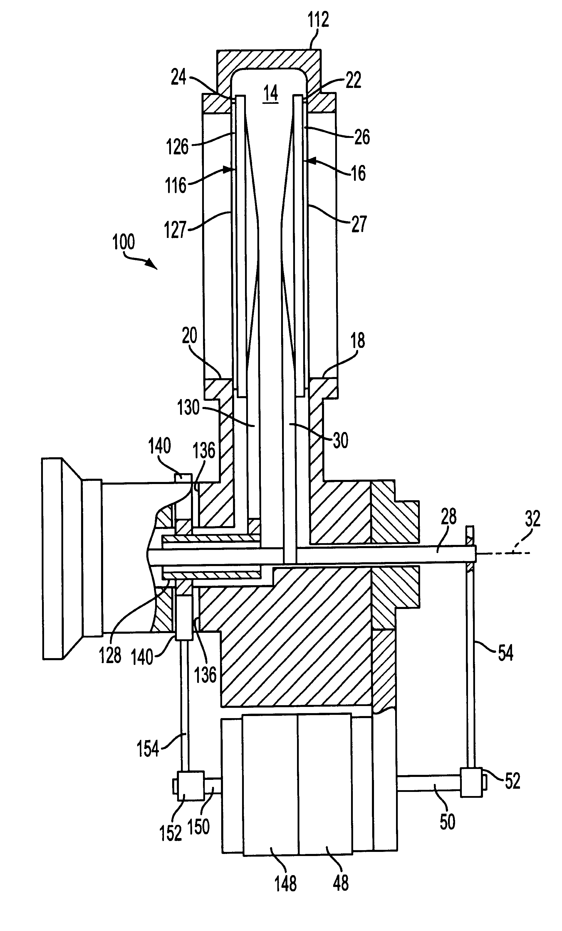
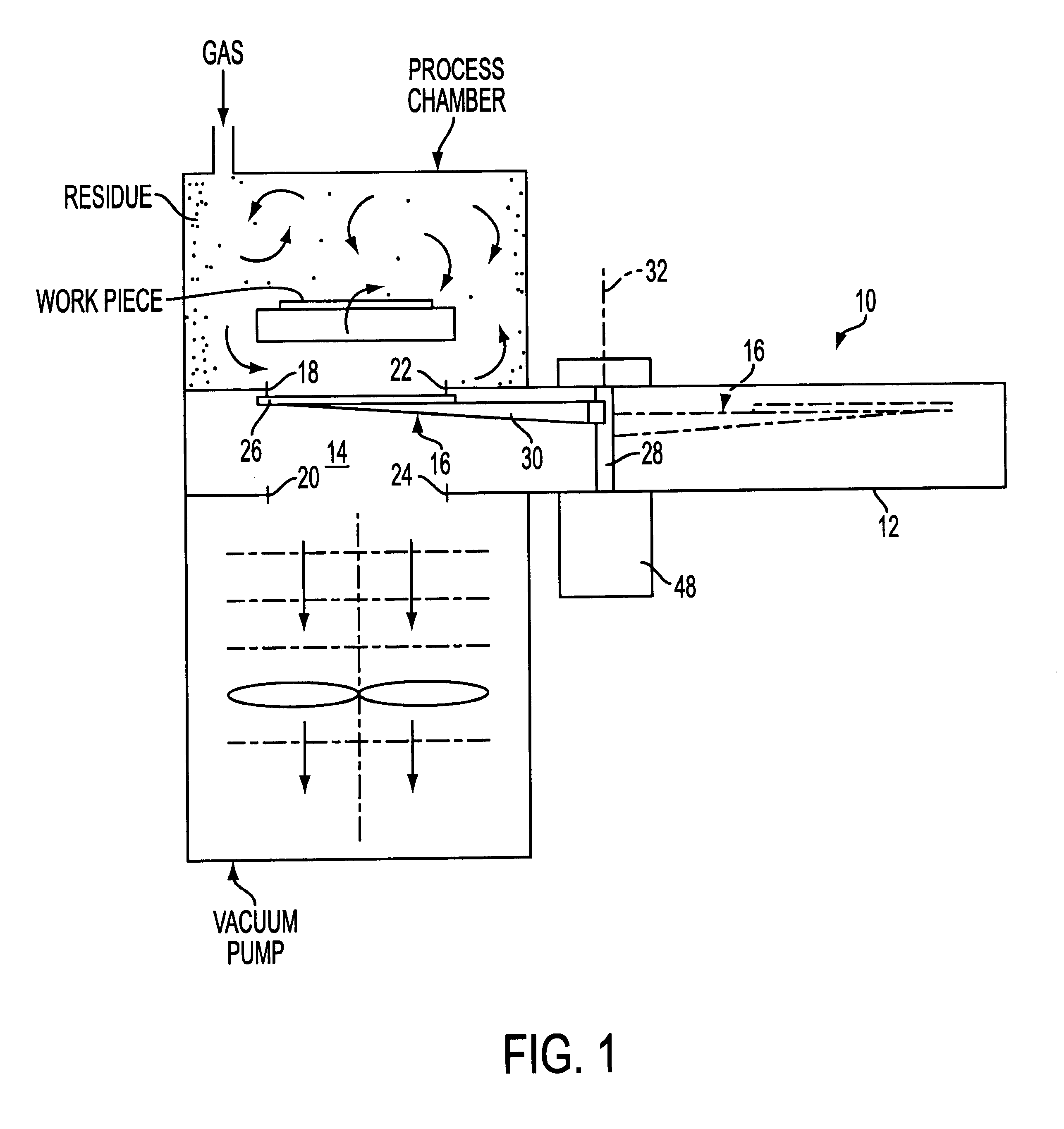
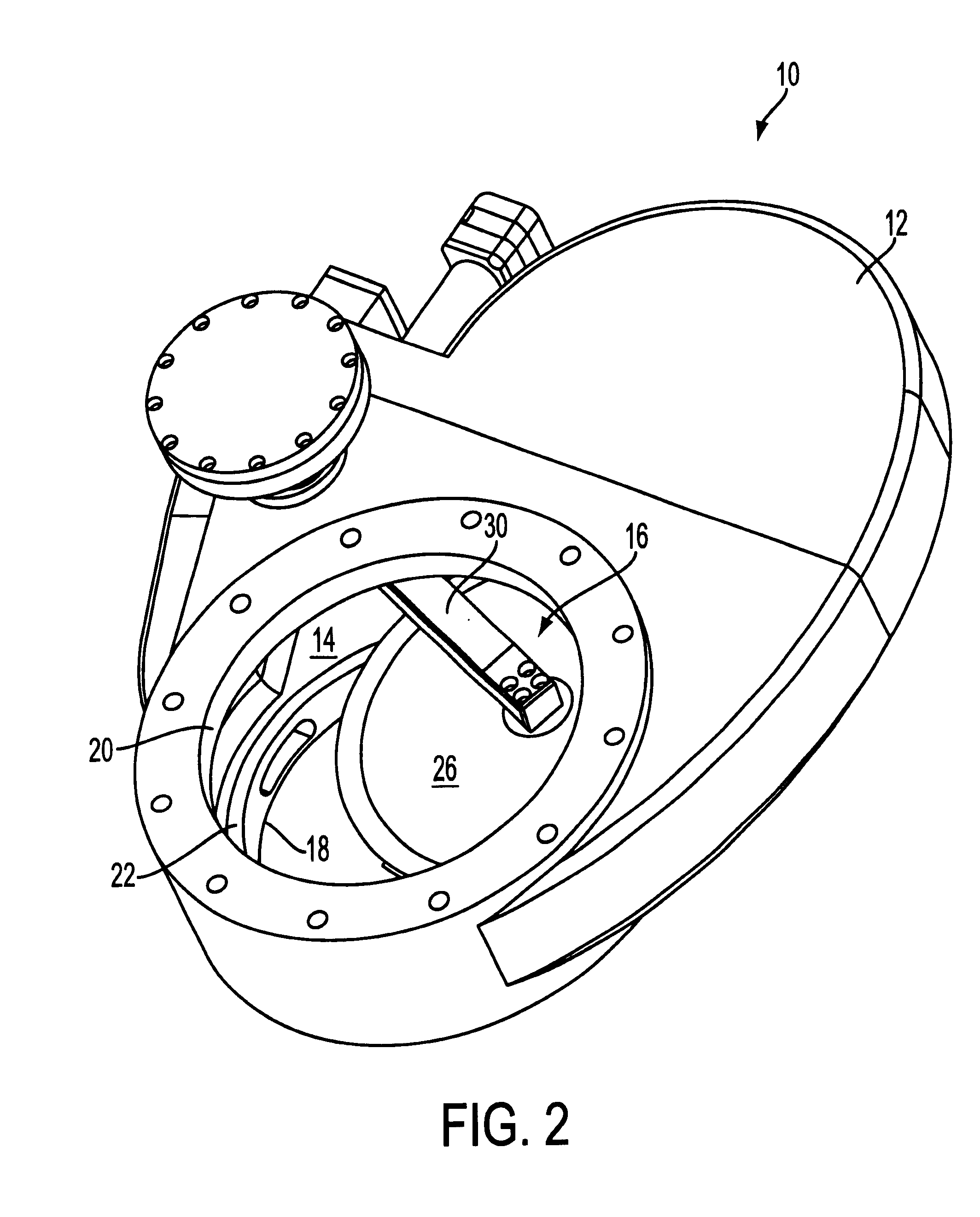
Referring to FIG. 1, a pendulum valve assembly 10 generally includes a housing 12 defining an interior space 14 containing a pendulum valve 16 and having a pair of opposing openings 18, 20 through which gas can enter and exit the interior space. Valve seats 22, 24 are provided in the interior 14 of the housing 12 around edges of the openings 18, 20. As its name implies, the pendulum valve 16 pivots between open and closed positions, and includes a valve body, which is provided as a disk 26, connected to a rotatably shaft 28 by a pivot arm 30 extending laterally from the shaft.

As shown, the first of the openings 18 of the pendulum valve assembly 10 can, for example, be connected to a process chamber and a second of the openings 20 can be connected to a vacuum pump to form a portion of a high purity gas delivery system, such as those used in semiconductor manufacturing or other thin film coating processes performed at very low pressures (high vacuums), e.g., a pressure on the order of...


PUM


Abstract

A dual pendulum valve assembly including a housing having an interior space and first and second openings through which fluid can enter and exit the interior space; valve seats disposed in the interior space around the edges of the openings; and first and second pendulum valves for opening and closing, respectively, the first and second openings. Each pendulum valve is independently movable and includes a valve body mounted relative to the housing so that the valve body is movable between a completely opened position wherein fluid is allowed to pass through its respective opening and a completely closed position wherein the valve body seals the opening so that fluid can not pass therethrough. Each pendulum valve also includes a shaft fixedly coupled to the valve body through at least one pivot arm and at least partially mounted within the housing so that the valve body can rotate about a longitudinal axis of the shaft between a first angular position where the first valve body is in the completely opened position and a second angular position where the valve body is substantially axially aligned with its respective opening, and move substantially parallel to the longitudinal axis of the shaft, so that the valve body can move between the second angular position and the completely closed position as the pendulum valve continues to rotate. The present disclosure also provides a method of precisely controlling vacuum pressure within a process chamber of a semi-conductor wafer fabricator.

Description

FIELD OF THE DISCLOSUREThe present disclosure relates to gate valve assemblies, and more particularly to a dual pendulum valve assembly comprising a process chamber isolation valve and a vacuum pump isolation valve. The vacuum pump isolation valve is useful for isolating a vacuum pump coupled to the pendulum valve assembly so that the vacuum pump is not exposed to the atmosphere during cleaning of the pendulum valve assembly and process chamber.BACKGROUND OF THE DISCLOSUREA pendulum valve assembly generally includes a housing containing a pendulum valve and including an interior space and a pair of openings through which gaseous fluid can enter and exit the interior space. As its name implies, a pendulum valve pivots between open and closed positions, and includes a valve body, which is usually provided as a disk, connected to a rotatably shaft by a pivot arm. In a completely opened position the disk of the pendulum valve is moved out of the flow path defined by the openings so that...

Claims


Application Information

Patent Timeline
IPC IPC(8): F16K3/10F16K3/02F16K3/06F16K3/04F04B39/10F16K31/04F16K31/524F16K31/53
CPCF16K3/06F16K3/10F16K51/02Y10T137/87981Y10T137/86083Y10T137/0318Y10T137/87917
Inventor MAHER, JOSEPH
Owner MKS INSTR INC
Why Eureka
Try Eureka