Method of characterizing partial coherent light illumination and its application to serif mask design

a technology of partial coherent light and mask design, applied in the field of photolithography, can solve problems such as real too many combinations

Inactive Publication Date: 2001-12-11
IBM CORP
View PDF9 Cites 21 Cited by
  • Summary
  • Abstract
  • Description
  • Claims
  • Application Information

AI Technical Summary

Problems solved by technology

The difficulty in this approach is that there are really too many combinations--it is 2 pixels.

Method used


Image

  • Method of characterizing partial coherent light illumination and its application to serif mask design
  • Method of characterizing partial coherent light illumination and its application to serif mask design
  • Method of characterizing partial coherent light illumination and its application to serif mask design

Examples


Embodiment Construction

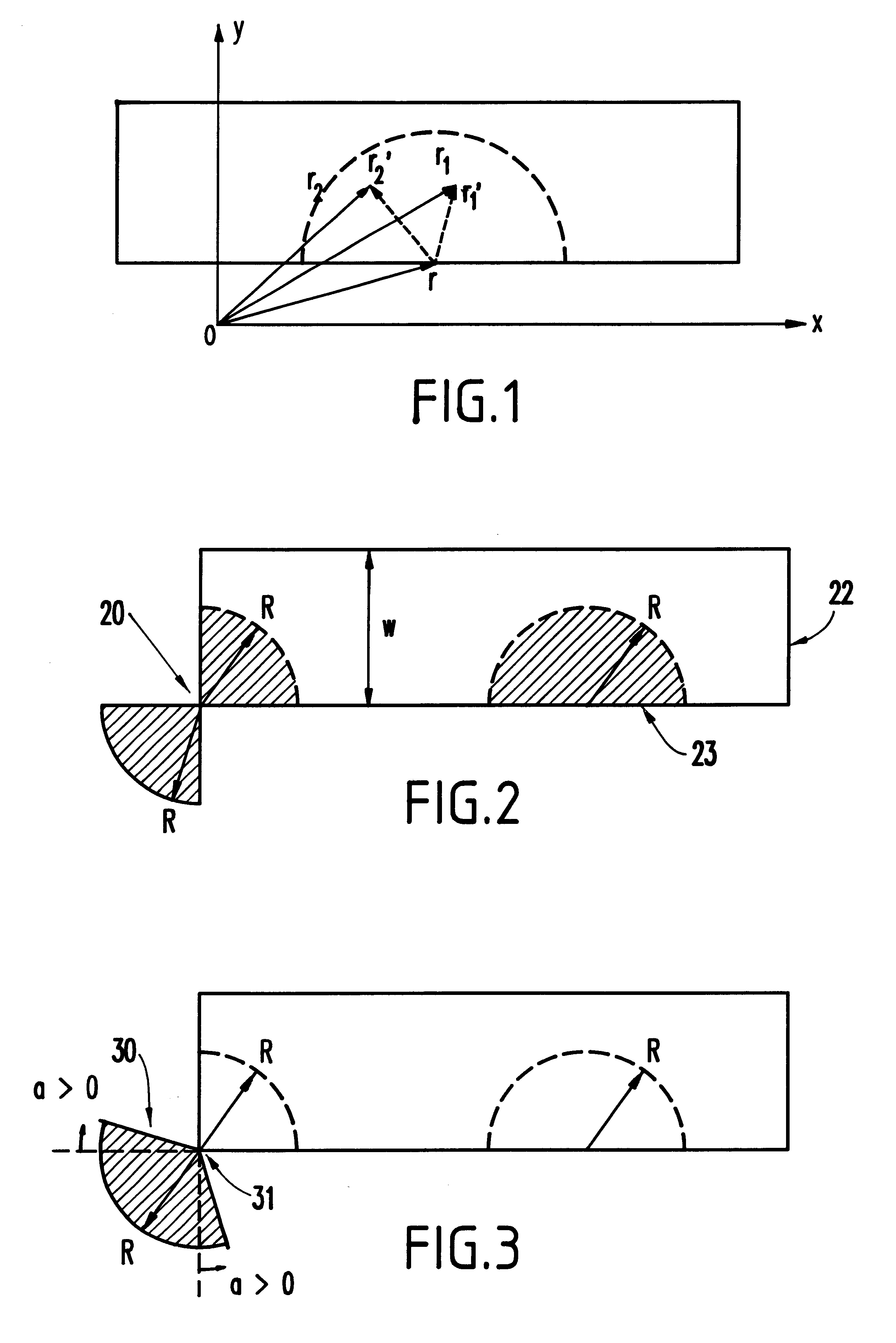
The invention characterizes partial coherent light illumination and uses this characterization to produce optical proximity correction. The characterization process begins by introducing many local coordinate systems, one for each position r at which the invention is going to find its aerial image intensity. For a position r, the invention introduces a local coordinate system centered at r. The invention uses a prime to indicate a coordinate in the local coordinate system. For a point with coordinate r in the global coordinate system, its coordinate is r.sub.1' in the local coordinate system (see FIG. 1). The relationship between r.sub.1' and r, is r.sub.1' =r.sub.1 -r. Similarly, for a second point r.sub.2 , its coordinate in the local coordinate system is r.sub.2 ' with relationship r.sub.2 '=r.sub.2 -r.

The invention characterizes mutual intensity function in terms of local polar coordinates r'.sub.1 =(r'.sub.1, .phi.'.sub.1), and r'.sub.2 =(r'.sub.2, .phi.'.sub.2), ##EQU3##

which ...


PUM

PropertyMeasurementUnit
wavelengthaaaaaaaaaa

Abstract

A method and structure for serif mask design for correcting optical proximity effects in photolithography first characterizes a partial coherent light illumination from a photolithographic system and then utilizes the characterization results to perform serif mask design for the purpose of optical proximity corrections. The characterization of a partial coherent light illumination includes identifying an effective range of optical proximity effects for the photolithographic system, and focusing on slow-varying angle dependent terms in mutual intensity function, etc. The method and structure for serif mask design starts from ideal serif and hole design that work perfectly under a complete coherent illumination or under a complete incoherent illumination. For an outer corner, the initial design is a quarter-circle serif centered at the outer corner and located at the opposite quadrant of outer corner itself. The method then adjusts the size and shape of the serif until the image intensity at a point along the edge. For an inner corner, the initial design is a quarter-circle hole centered at the inner corner and located symmetrically inside the mask. The method then adjusts the size and shape of the serif until the aerial image intensity at the outer corner equals the aerial image intensity at a point along the edge.

Description

1. Field of the InventionThe present invention generally relates to photolithography and more particularly to an improved mask and mask design methodology.2. Description of the Related ArtPhotolithography is the technology of reproducing patterns using light. As presently used in semiconductor industry, a mask pattern for a desired circuit is transferred to a wafer through light exposure, development, etch, resist strip, etc. As the feature size on a circuit becomes smaller and smaller, the circuit shape on the wafer differs from the original mask pattern more and more. In particular, corner rounding, line end foreshortening, etc. are typically observed. These phenomena are called optical proximity effects.One of the main reasons for optical proximity effects is light diffraction. Optical proximity effects coming from light diffraction can be overcome partly if one has the choice of using a shorter wavelength source of light, with a projection system possessing a larger numerical ap...

Claims


Application Information

Patent Timeline
Patent Type & Authority Patents(United States)
IPC IPC(8): G03F7/20
CPCG03F7/70441
Inventor LU, NING
Owner IBM CORP
Why Eureka
Try Eureka