
Antenna selection control circuitry

a technology of selection control and circuitry, applied in the field of communication systems, can solve the problems of direct line of sight communication, power loss known as path loss, and the quality of communication between a transmitting unit and a receiving unit within the communication system, so as to improve the diversity performance of the antenna for a receiver, avoid clicks and other disturbing interferences in received information, and simple averaging of signals

Inactive Publication Date: 2001-12-11
NOKIA MOBILE PHONES LTD
View PDF17 Cites 90 Cited by
  • Summary
  • Abstract
  • Description
  • Claims
  • Application Information

AI Technical Summary

Benefits of technology

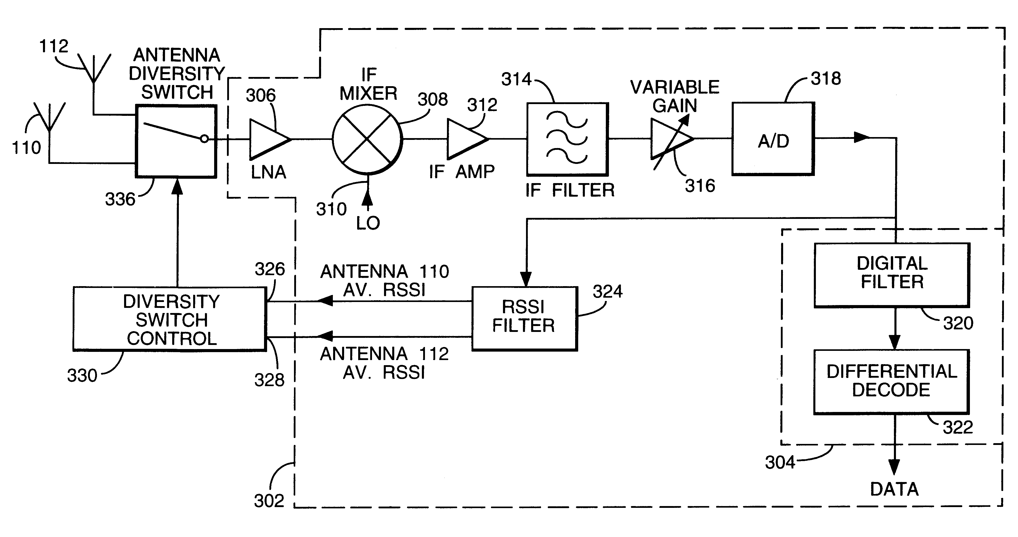
An advantage of the present invention is that antenna diversity performance for a receiver may be improved, since an antenna is selected when it has the greatest chance of receiving the best signal quality. This reduces the likelihood of having to switch antennas later whilst receiving information, and thereby avoids clicks and other disturbing interferences in received information due to phase changes caused by such switching. Furthermore, this improvement may be achieved with relatively simple averaging of signals. Additionally, a change in the typical quality of a received signal from an antenna can be taken into account and diversity biased towards that antenna. An example of such an instance is when a radio telephone is operated in an in-car mode, and external car mounted antennas are input to the radio telephone. In such circumstances, since both antennas are external, they typically have the same gain or sensitivity to signals as each other. If selection was biased towards one of the external car mounted antennas, then possibly higher quality signals received by the other car antenna would not be utilised.
is that antenna diversity performance for a receiver may be improved, since an antenna is selected when it has the greatest chance of receiving the best signal quality. This reduces the likelihood of having to switch antennas later whilst receiving information, and thereby avoids clicks and other disturbing interferences in received information due to phase changes caused by such switching. Furthermore, this improvement may be achieved with relatively simple averaging of signals. Additionally, a change in the typical quality of a received signal from an antenna can be taken into account and diversity biased towards that antenna. An example of such an instance is when a radio telephone is operated in an in-car mode, and external car mounted antennas are input to the radio telephone. In such circumstances, since both antennas are external, they typically have the same gain or sensitivity to signals as each other. If selection was biased towards one of the external car mounted antennas, then possibly higher quality signals received by the other car antenna would not be utilised.
Embodiments in accordance with the invention are contrary to the usual assumption that both antennas of an antenna diversity system have equal sensitivity. It is recognised that, even if both antennas have the same gain, because one is typically external and the other internal and / or placed in different locations to the other, the effective sensitivity or gain for the antenna is different. Moreover, due to the size constraints of radio telephones it is likely that an internal antenna is smaller than an external antenna, e.g. a helical antenna, and have a gain of 6 to 10 decibels lower than that of the external antenna. Additionally, as a user of a mobile terminal, for example, moves the environment changes and this may affect the effective gain. The effective gain of an antenna may be indicated by the RSSI value for the antenna.
Since one antenna, typically an external antenna, usually receives signals of greater strength than the other, usually internal, antenna, simple switching between antenna based solely on instantaneous RSSI, or some other signal quality measure, can result in an antenna being selected which is likely to receive signals of lower strength or poorer signal quality. Thus, lower quality signals may be input to a receiver than might actually be available from another antenna.
In a preferred embodiment the first antenna comprises an inherent likelihood of receiving subsequent signals having the best signal quality. This typically occurs when the first antenna is disposed outside the housing of a communication apparatus e.g. radio telephone, and the second antenna is disposed inside the housing.
The antenna selection apparatus may further comprise a comparing means for comparing long term average received signal quality for respective first and second antenna, and designating the first or second antenna having the best long term average received signal quality as the antenna having the likelihood of receiving subsequent signals having the best signal quality.

Problems solved by technology

Existing communication systems suffer from a number of effects which act to degrade the quality of communication between a transmitting unit and a receiving unit within the communication system.
Since the base station and radio telephone are close to ground level obstacles such as buildings, walls, cars and people inhibit direct line of sight communication between them, especially in urban areas.
This power loss is known as path loss.
The effect of the periodic nulls in received signal power due to Rayleigh fading is that transmitted data may be lost thereby introducing errors into the transmission.
This results in a reduced information or data handling capacity for the network.
Additionally, the multiple signal paths introduce time delays between signals incident at a particular radio telephone which causes inter-symbol interference.
Such symbol interference is a particular problem in communication systems having relatively high data rates, for example where 1 / symbol rate >10 .mu.s.
In a system having relatively low data rates, for example >25k symbol / s, the periodic variation in the signal strength due to Rayleigh fading is the main problem.
Additionally, as a user of a mobile terminal, for example, moves the environment changes and this may affect the effective gain.
Since one antenna, typically an external antenna, usually receives signals of greater strength than the other, usually internal, antenna, simple switching between antenna based solely on instantaneous RSSI, or some other signal quality measure, can result in an antenna being selected which is likely to receive signals of lower strength or poorer signal quality.
At such BER levels the communication channel begins to degrade and the degradation results in audible clicks or pops.

Method used


Image

  • Antenna selection control circuitry
  • Antenna selection control circuitry
  • Antenna selection control circuitry

Examples


Embodiment Construction

Embodiments of the invention will now be described, by way of example only, and with reference to the accompanying drawings in which:

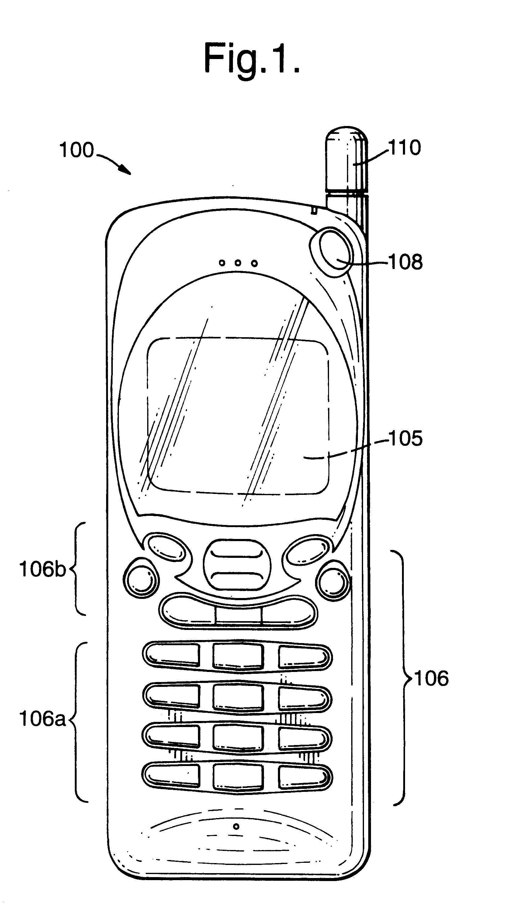
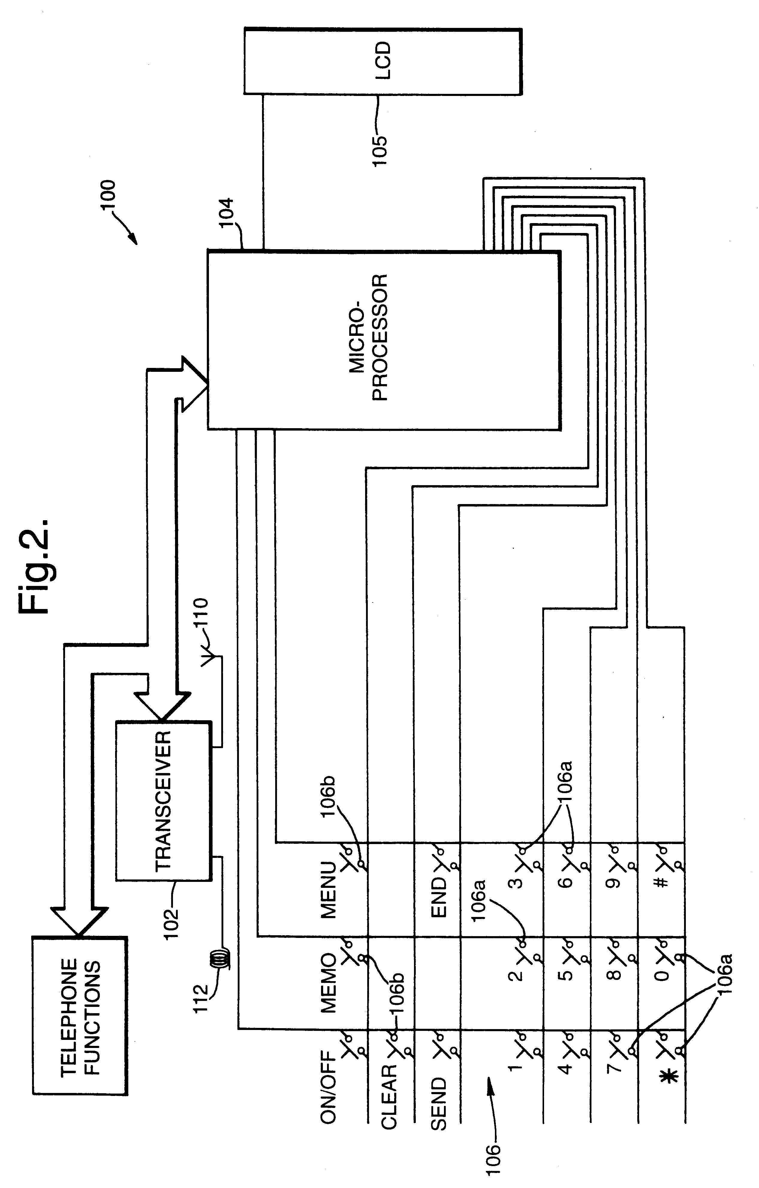
The portable radio telephone shown in FIG. 1 is a cellular telephone 100 powered by a rechargeable battery pack. The user-interface of telephone 100 comprises a display, e.g. a liquid crystal display 105, itself well-known in the art and a keypad 106 on the front of the telephone 100. The display is coupled to and regulated by the microprocessor 104 in the usual manner. The keypad 106 essentially comprises two main sets of keys, namely alpha numeric keys 106a associated with alpha numeric data especially for dialling telephone numbers, but also (optionally) for entering alphanumeric data into the telephone memories, e.g. a subscriber number index, and a set of function keys 106b for enabling various predetermined functions or operations. The telephone 100 also includes a power ON / OFF button 108, an external antenna 110, (typically a retractable antenna...


PUM


Abstract

Apparatus and method are described for selecting for subsequent use an antenna from a plurality of antennas. The selection is biased in favor of the antenna most likely to receive subsequent signals having best signal quality. In a preferred embodiment the signal quality comprises received signal strength.

Description

The present invention relates to apparatus and a method for controlling the selection of an antenna for a receiver operable for at least two antennas. In particular, but not exclusively, the present invention relates to antenna selection control circuitry for a communication system such as a radio telephone network.BACKGROUND TO INVENTIONExisting communication systems suffer from a number of effects which act to degrade the quality of communication between a transmitting unit and a receiving unit within the communication system. In particular, in a radio telephone network for example, which comprises a plurality of mobile stations or radio telephones communicating with a base station connected to other base stations in the radio telephone network, both the radio telephone and the base station are relatively close to ground level. Since the base station and radio telephone are close to ground level obstacles such as buildings, walls, cars and people inhibit direct line of sight commu...

Claims


Application Information

Patent Timeline
IPC IPC(8): H04B7/08H04B7/26
CPCH04B7/0808
Inventor JAGER, MICHAEL DAVID
Owner NOKIA MOBILE PHONES LTD
Learn More