Pressure feedback signal to optimise combustion air control

a pressure feedback and control technology, applied in the field of combustion systems, can solve the problems of not suitably designed, affecting the effect of combustion air control, and reducing the purpose of burning off burners,

Inactive Publication Date: 2001-12-25
HOWLETT MICHAEL +2
View PDF16 Cites 65 Cited by
  • Summary
  • Abstract
  • Description
  • Claims
  • Application Information

AI Technical Summary

Problems solved by technology

Therefore, as more burners are shut-off, increasing amounts of air (and gas) will go to the remaining burners, partially defeating the purpose (less heat input) of shutting off the burners.
These systems are generally complex and thus expensive and are not suitably designed for a simple air valve repositioning.

Method used


Image

  • Pressure feedback signal to optimise combustion air control
  • Pressure feedback signal to optimise combustion air control
  • Pressure feedback signal to optimise combustion air control

Examples


Embodiment Construction

Physical Description

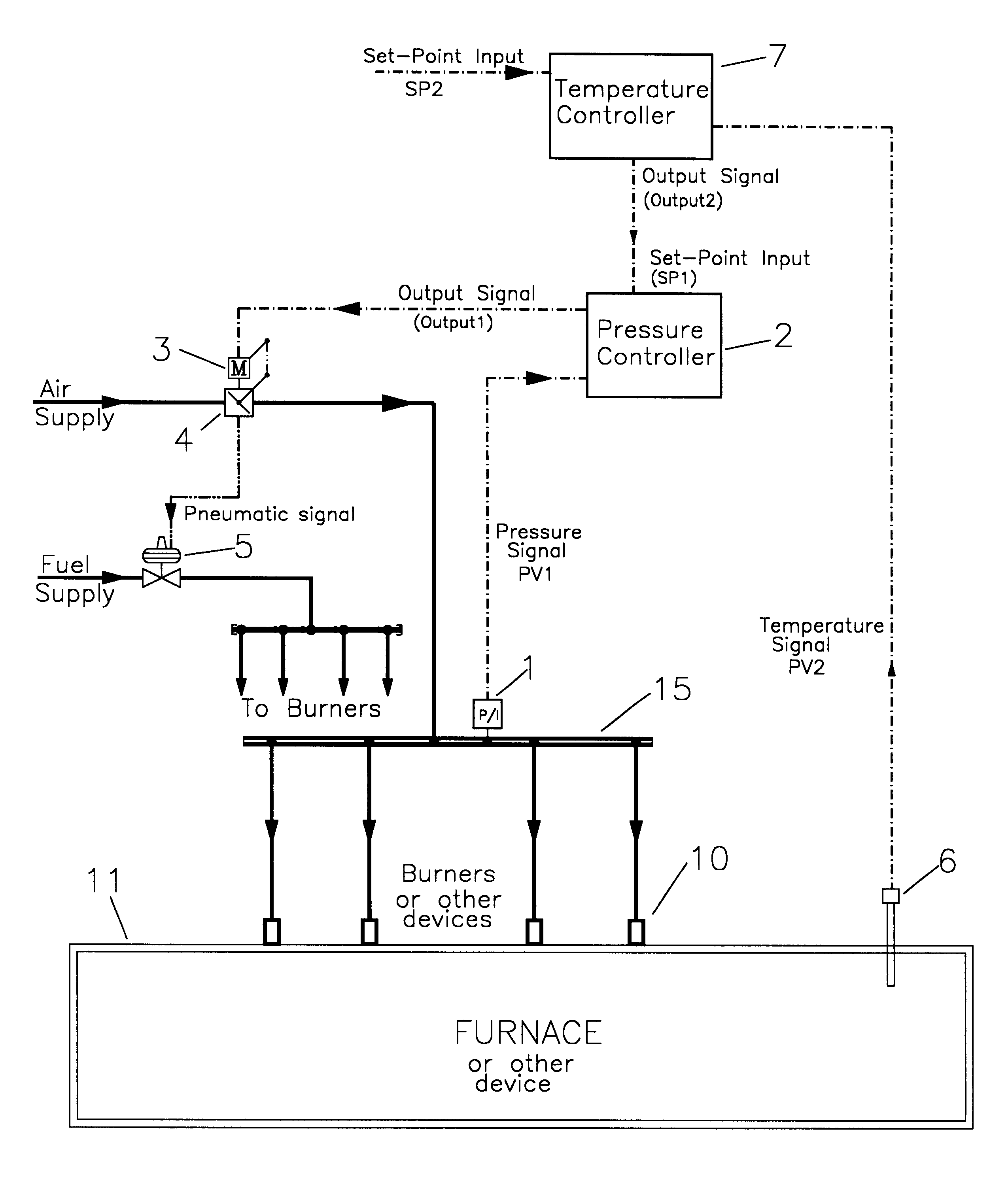
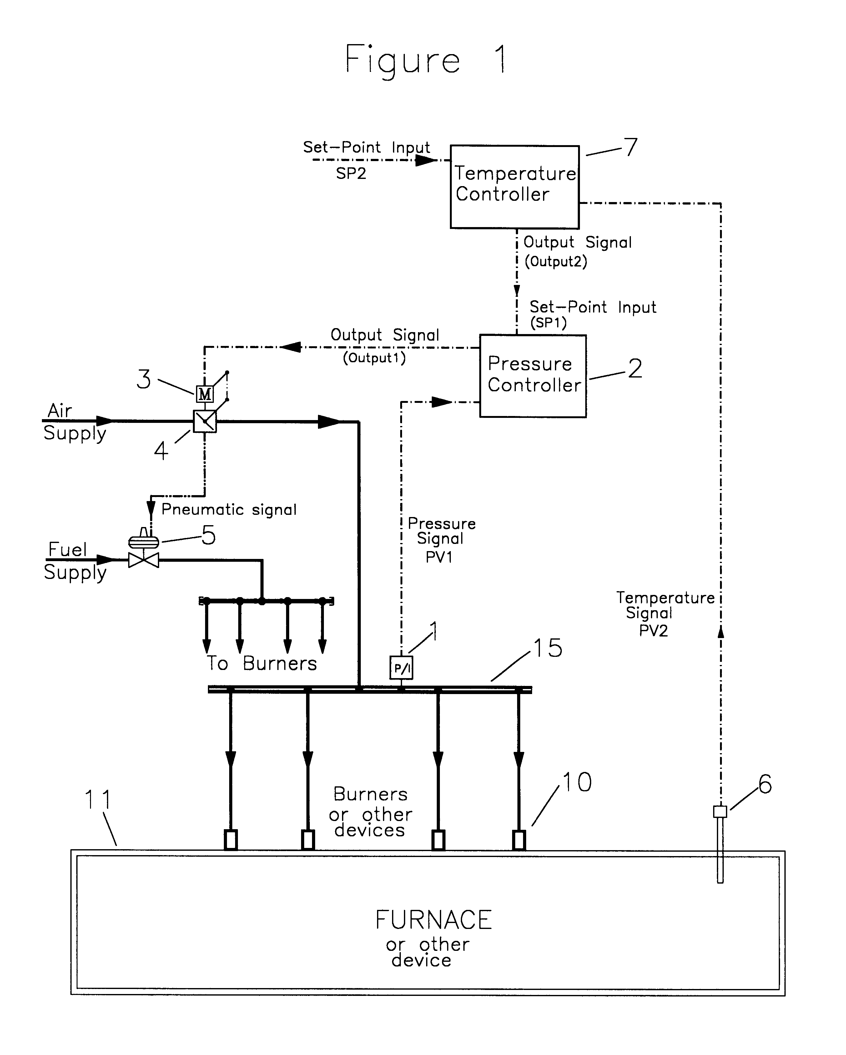
A pressure transducer (Item 1, FIG. 1) measures the pressure in an air manifold (Item 15, FIG. 1), at a point that is both; upstream of multiple burners (or other devices), and downstream of an air flow control device such as an air flow control valve (Item 4, FIG. 1). The pressure transducer is generally a differential pressure transmitter (with one side open to atmospheric pressure) of about 0-1.5 PSIG (pounds per square inch gage) pressure range with a proportional output signal (generally 4-20 mA (milliamps) or 0-10 volts). A pressure controller (Item 2, FIG. 1) can be any microprocessor based electronic instrument capable of; receiving a remote set-point input (generally 4-20 mA), calculating a PID (proportional, integral and derivative) control loop, and sending a proportional output signal (generally 4-20 mA). The air flow control valve can be a butterfly, ball, adjustable port, gate, globe or other type that is suitably sized for the air flow range and th...


PUM


Abstract

A novel method of combustion air control for multiple burner furnaces, whereas a pressure transducer is located in the air piping downstream of each zone air flow control device. The pressure transducer sends a feedback signal to a pressure control loop that is in a logical cascade from the furnace temperature control loop. The pressure control loop repositions the air flow control device to compensate for changes in both downstream and upstream conditions. Output from the temperature control loop is interpreted by the pressure control loop as a changing remote set-point value. In one embodiment, the system is ideally suited to compensate for the pressure drop changes that occur across a zone air flow control valve, when flow rate changes occur as burners are started or stopped, thus providing a substantially higher turndown ratio and better control at low fire settings.

Description

BACKGROUND--FIELD OF INVENTIONThis invention relates to combustion systems primarily where there is more than one burner in a controlled zone or section.BACKGROUND--Discussion of Prior ArtAt the present time, there are four basic types of combustion control systems used in multiple burner furnaces. They are; pressure balance control, linked valve control, flow balance control and mass flow control.In the first three cases, a single flow control valve is normally used to control the combustion air flow to a group (zone) of burners. This valve is usually actuated by a valve actuator (electric control motor) through mechanical linkages. Control of the valve actuator is by an output signal from the furnace zone temperature controller. The controller sends an output signal to the valve actuator that proportionally positions the air flow control valve. Thus a 10% output signal will position the valve in the 10% open position and the 70% output signal positions the valve in a 70% open posi...

Claims


Application Information

Patent Timeline
Patent Type & Authority Patents(United States)
IPC IPC(8): F23N1/02F23N5/02F23N1/08F23N1/10F23N5/18
CPCF23N1/027F23N1/10F23N5/022F23N2005/181F23N2225/04F23N2225/06F23N2225/08F23N2235/06F23N2235/16F23N2235/20
Inventor HOWLETT, MICHAELMURRAY, GORDON ALEXANDERCROWLE, WILLIAM E.
Owner HOWLETT MICHAEL
Why Eureka
Try Eureka