Utility lighter

a technology for utility lighters and lighters, applied in firelighters, burners, combustion processes, etc., can solve problems such as ineffective on/off switches, drawbacks in positions, and unintended users, and achieve a greater resistance level

Inactive Publication Date: 2001-12-25
SOC DITE SOC BIC
View PDF84 Cites 37 Cited by
  • Summary
  • Abstract
  • Description
  • Claims
  • Application Information

AI Technical Summary

Benefits of technology

The present invention relates to lighters having greater level of resistance for unintended users. The lighter comprises a housing with a nozzle having an outlet, and a fuel supply in communication with a fuel conduit adapted for selective release of fuel to the nozzle outlet. A valve actuator is included for engaging a valve to release fuel. A release member is included, and is slidably supported by the housing at a first end and unsupported at a s

Problems solved by technology

However, the on/off switches that must be positively moved by the user between "on" and "off" positions have drawbacks.
For example, an adult user may forget to move the switch back to the "off" position after use and thereby

Method used


Image

  • Utility lighter
  • Utility lighter
  • Utility lighter

Examples


Embodiment Construction

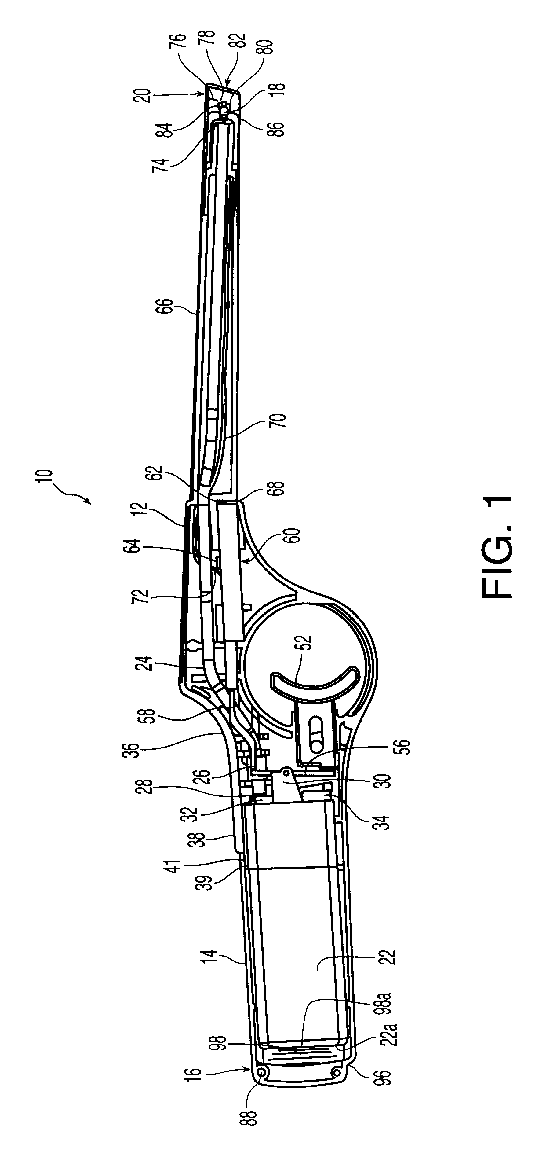
Turning to FIG. 1, a preferred embodiment of a utility lighter 10 constructed in accordance with the present invention generally includes a housing 12 which may primarily be formed of a molded rigid polymer or plastic materials such as acrylonitrile butadiene styrene terpolymer (ABS), or the like. Housing 12 includes a handle 14 disposed toward the back of the lighter 10, proximate to a first end 16. It should be noted that the term back, as used herein, refers to that portion which is closest to first end 16 and the term front, as used herein, refers to that portion which is closest to a second end 20 of lighter 10. It will be noted that the terms first end 16 and second end 20 are used to describe the preferred embodiments and form no part of the present invention.

A nozzle 18 is disposed proximate the second end 20 for emitting fuel to sustain a flame as will be described herein. Handle 14 preferably contains a fuel supply container 22, which may be a conventional butane fuel cell...


PUM


Abstract

The present invention relates to a lighter including a housing having a handle at one end and a nozzle at another end and including a fuel supply connected for selective fluid communication with the nozzle. A release member is cooperatively connected to the housing to initiate the flow of fuel from the fuel supply to the nozzle. An ignitor, such as a piezoelectric mechanism, is provided for generating a spark proximate the nozzle. A trigger spaced from the release member is operatively connected to the housing for actuating the ignitor for the generation of a spark igniting the fuel present at the nozzle.

Description

TECHNICAL FIELDThe present invention generally relates to general purpose utility lighters such as those used to ignite candles, barbecue grills, fireplaces and campfires.BACKGROUND OF THE INVENTIONLighters used for igniting tobacco products, such as cigars, cigarettes, and pipes, have developed over a number of years. Typically, these lighters use either a rotary friction element or a piezoelectric element to generate a spark in proximity to a nozzle emitting fuel from a fuel container. Piezoelectric mechanisms have gained universal acceptance. One such piezoelectric mechanism is disclosed in U.S. Pat. No. 5,262,697 ("the '697 patent"). The disclosure of the '697 patent is incorporated by reference herein.Lighters have also evolved from the small, hand-held lighters to several forms of extended lighters. These lighters are also hand held, but are more useful for general purposes such as lighting candles, barbecue grills, fireplaces and campfires. Earlier attempts at such designs re...

Claims


Application Information

Patent Timeline
IPC IPC(8): C10L11/00F23Q2/00F23Q2/28F23Q7/12F23Q2/34F23Q2/36
CPCC10L11/00F23Q2/287F23Q2/28
Inventor ADAMS, PAULTUBBY, BRIANORAZIETTI, RICHARD M.
Owner SOC DITE SOC BIC
Why Eureka
Try Eureka