Motor drive unit and method of detecting malfunction of motor drive unit

a technology of motor drive and malfunction detection, which is applied in the direction of electrical steering, dc motor rotation control, transportation and packaging, etc., can solve the problem of useless motor drive uni

Inactive Publication Date: 2002-01-01
TOYOTA JIDOSHA KK
View PDF4 Cites 36 Cited by
  • Summary
  • Abstract
  • Description
  • Claims
  • Application Information

AI Technical Summary

Problems solved by technology

However, the aforementioned motor drive unit takes into account nothing but the possibility of the portion between one terminal of the electric motor and the grounded line being short-circuited.
Therefore, this motor drive unit is useless when there is a malfunction occurring in a motor drive device, a malfunction detection controller, or the like.

Method used


Image

  • Motor drive unit and method of detecting malfunction of motor drive unit
  • Motor drive unit and method of detecting malfunction of motor drive unit
  • Motor drive unit and method of detecting malfunction of motor drive unit

Examples


Embodiment Construction

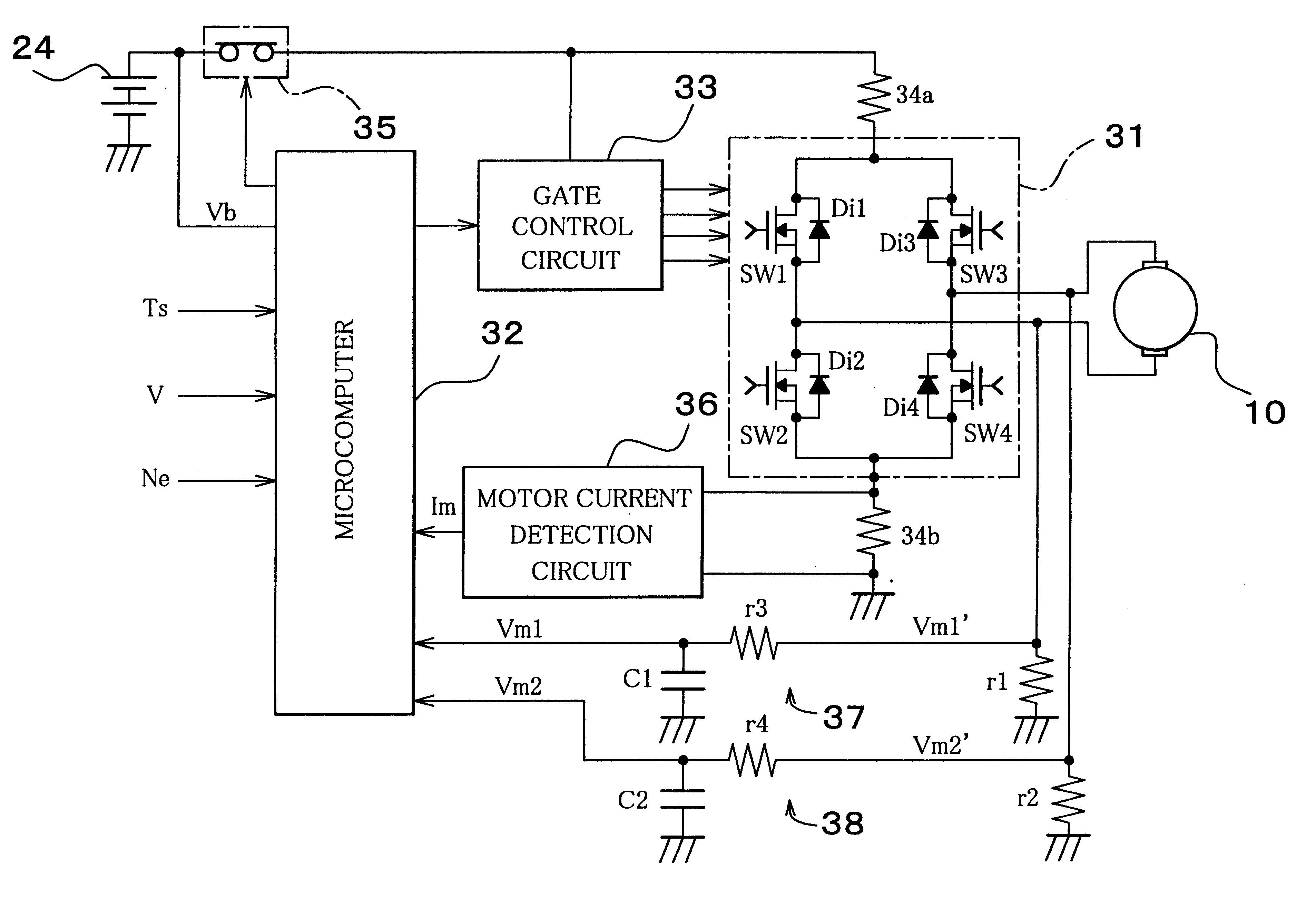
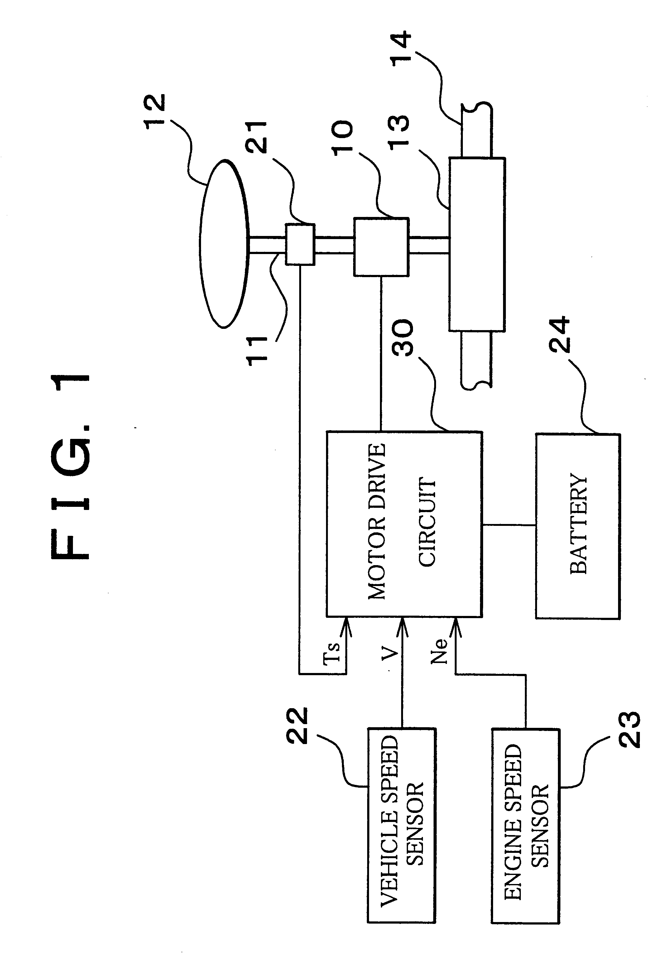
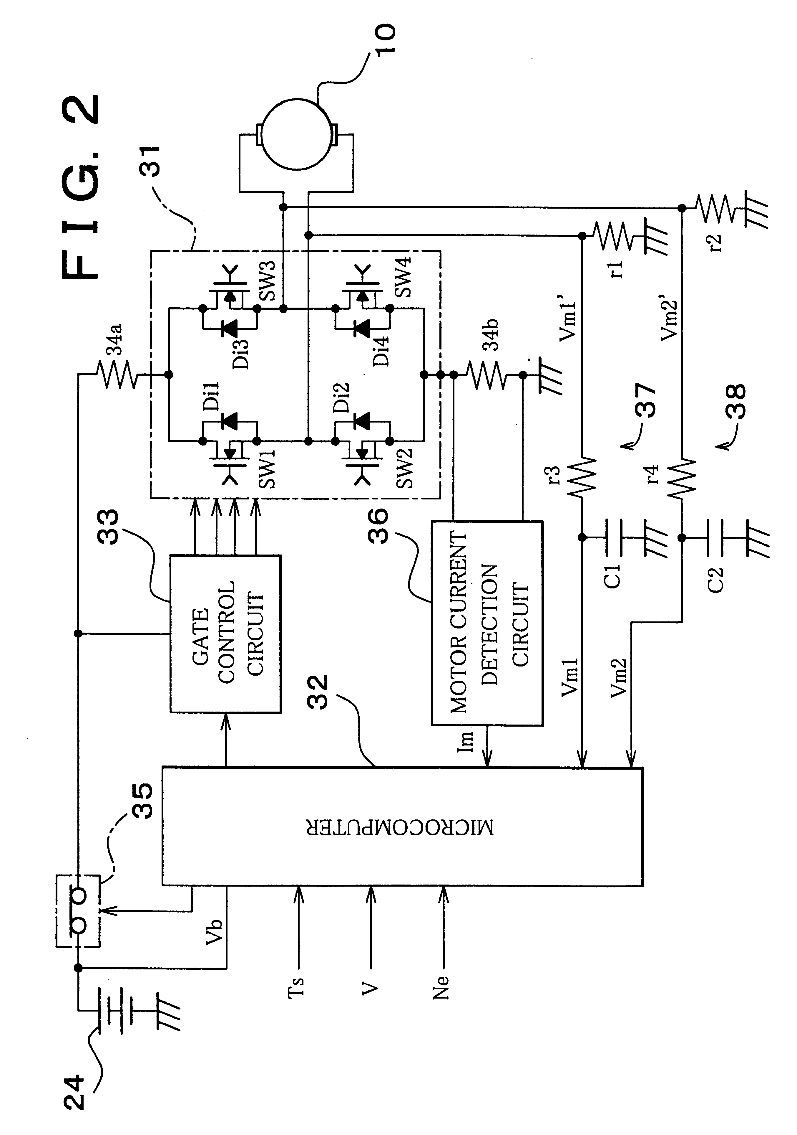
Hereinafter, one embodiment of the invention will be described with reference to the drawings. FIG. 1 schematically shows a vehicular motor-driven power steering device to which a motor drive unit in accordance with the invention is applied.

This motor-driven power steering device has a DC motor 10 serving as an electric motor.

The DC motor 10 is mounted to an intermediate portion of a steering shaft 11 to rotate the steering shaft 11, and applies an assisting force to assist the steering of front wheels by rotational operation of a steering handle 12. A lower end portion of the steering shaft 11 is connected to a tie rod 14 in a steering gear box 13 in a manner allowing power transmission. The tie rod 14 is axially displaced due to rotation of an axis of the steering shaft 11. Front wheels (not shown) are steerably connected to the ends of the tie rod 14. The front wheels are laterally steered due to axial displacement of the tie rod 14.

A steering torque sensor 21 is mounted to the s...


PUM


Abstract

A DC motor is connected to diagonal positions of a bridge circuit having of four sides including switching elements and reflux diodes. At least one of two terminals is connected to a power line, and at least the other terminal is grounded. By performing pulse width modulation control of the switching elements, operation of the DC motor is controlled. When the DC motor is in operation, the sum of the terminal voltages of the DC motor is equal to the power voltage. When the DC motor is out of operation, the sum of the voltages is set to a predetermined voltage. If the sum of the voltages has deviated from the power voltage or the predetermined voltage by at least a predetermined value, the occurrence of a malfunction is judged.

Description

INCORPORATION BY REFERENCEThe disclosure of Japanese Patent Application No. 11-252593 filed on Sep. 7, 1999 including the specification, drawings and abstract is incorporated herein by reference in its entirety.1. Field of the InventionThe invention relates to a motor drive unit which controls an electric motor through pulse width modulation (PWM) control and to detection of a malfunction for the motor drive unit.2. Description of the Related ArtAt present, there is a motor drive unit which controls an electric motor. The motor drive unit has a bridge circuit composed of four sides that each have a switching element. The electric motor has at least two ends connected to the switching elements that are diagonally positioned in relation to the bridge circuit. At least one of the switching elements is connected to a power line, and at least one of the other switching elements is grounded. The motor unit is driven by applying voltage to the power switching element. By performing pulse w...

Claims


Application Information

Patent Timeline
Patent Type & Authority Patents(United States)
IPC IPC(8): B62D5/04H02H7/08H02P7/00H02P6/06H02P6/08H02P6/12H02P6/26H02P6/28
CPCB62D5/0487H02P7/0044H02H7/0838Y10S388/903H02P7/0094H02P7/04B62D5/04
Inventor KASAI, EIJIFUJITA, SHUJI
Owner TOYOTA JIDOSHA KK
Why Eureka
Try Eureka