Low voltage mixer

a low-voltage mixer and mixer technology, applied in the field of low-voltage mixers, can solve the problems of reducing the dynamic range of the typical balanced mixer operated with such a low supply potential, affecting the efficiency of some additional elements, and causing the addition of additional expense and inefficiency of some additional elements

Inactive Publication Date: 2002-01-01
SIGE SEMICON
View PDF1 Cites 19 Cited by
  • Summary
  • Abstract
  • Description
  • Claims
  • Application Information

AI Technical Summary

Problems solved by technology

Energizing current is usually supplied with a potential of not more than about 3 volts, however such low voltage is less than convenient for the operation of the typical balanced mixer circuit.
The dynamic range of the typical balanced mixer operated with such a low supply potential is reduced such as to be impractical.
A greater operating potential for the balanced mixer can ameliorate this problem but with consequential added expense and inefficiency of some additional element such as a DC to DC inverter for example.

Method used


Image

  • Low voltage mixer
  • Low voltage mixer
  • Low voltage mixer

Examples


Embodiment Construction

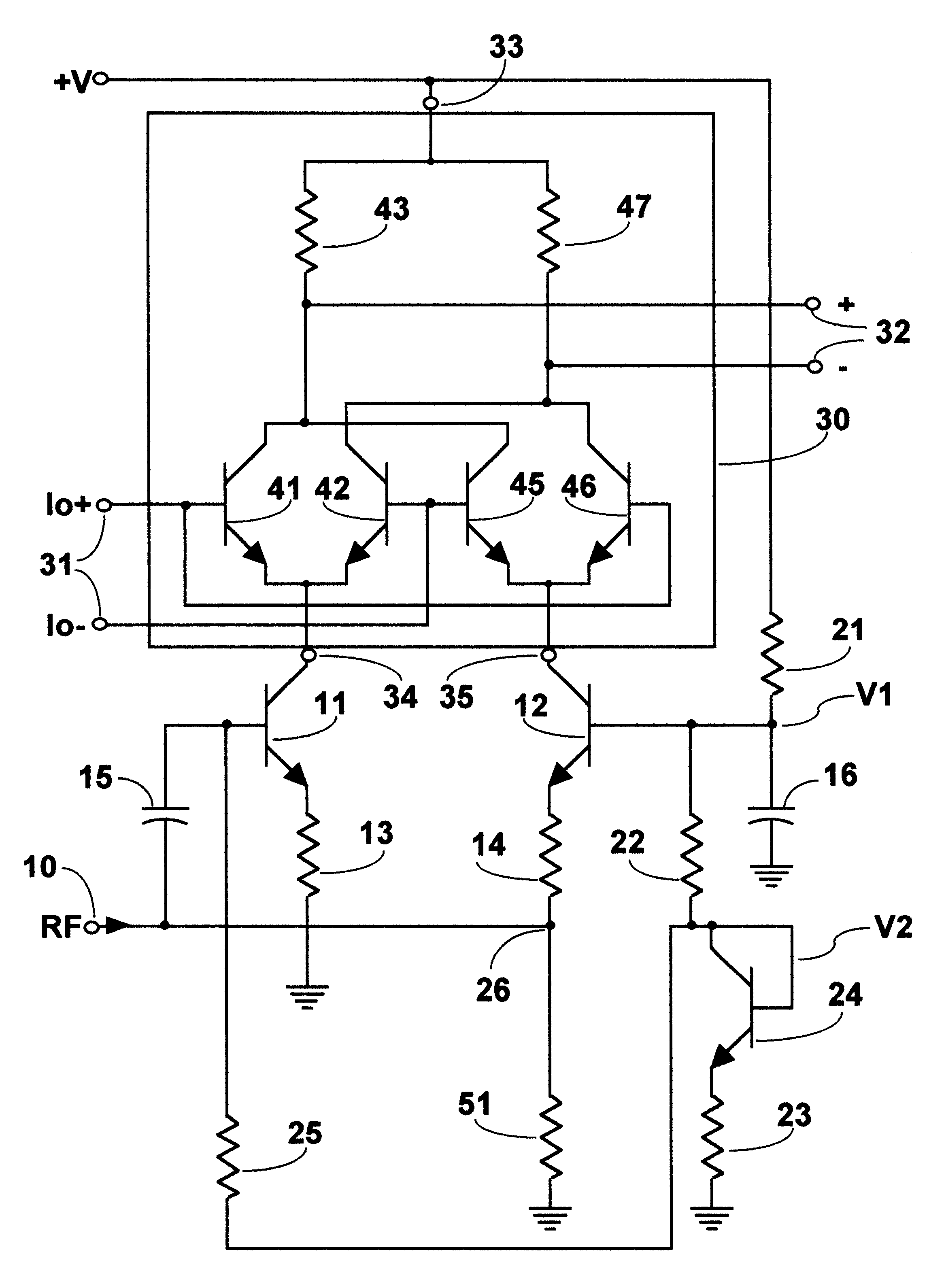
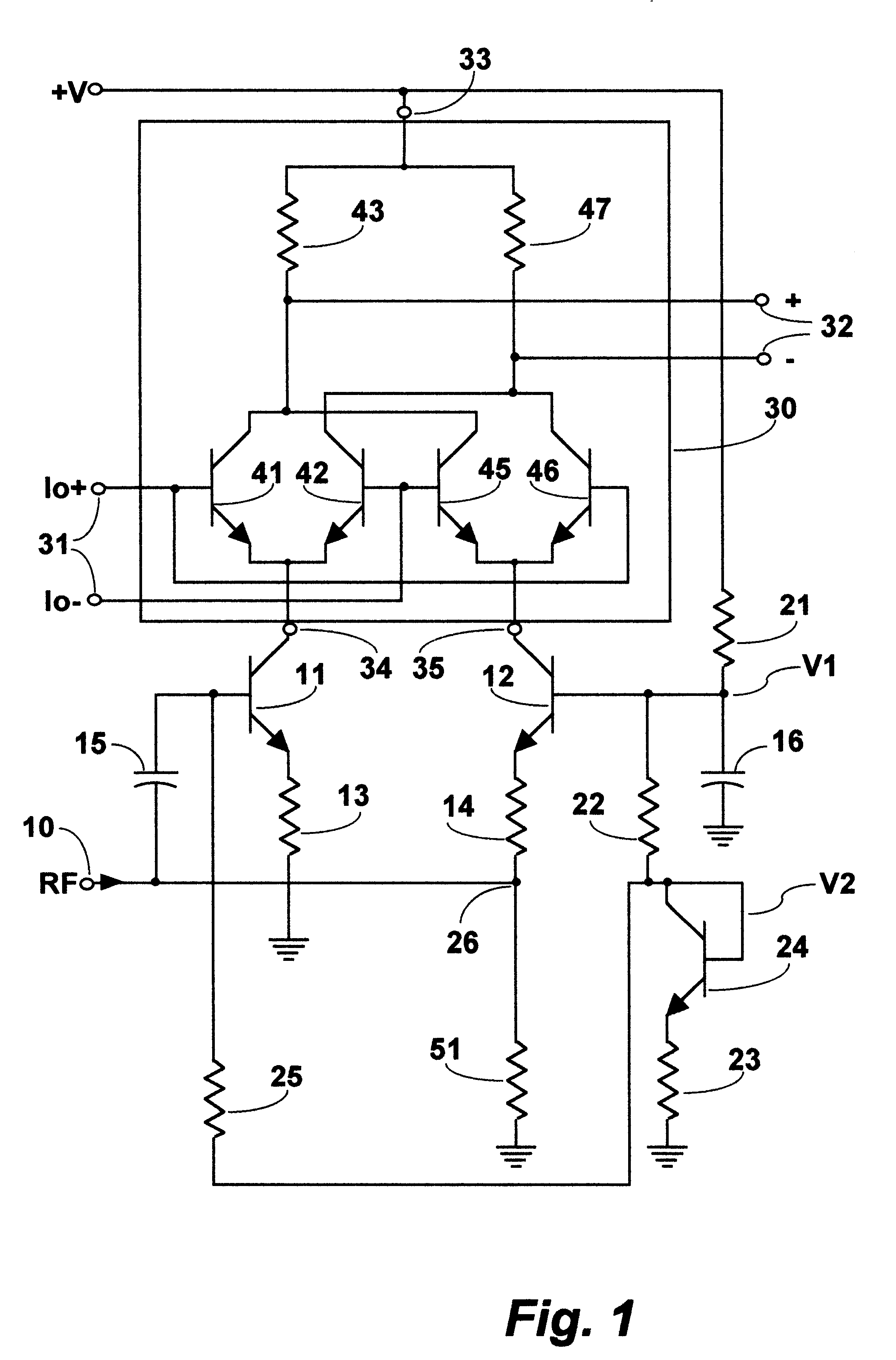
In FIG. 1 the mixer is provided with a single ended input port 10, for receiving radio frequency (RF) signals. The mixer is energized for operation with operating power via a power terminal +V and ground terminals. In this example the mixer illustrated is intended for use with a low voltage power source, a 3 volt battery, not shown. Input signals received via the single ended input port 10 and being of desired frequencies are converted by a balanced mixer 30 to output signals which are provided at a balanced signal output port 32.

The balanced mixer circuit 30 includes a first differential amplifier having first and second transistors 41 and 42, and a second differential amplifier having first and second transistors 45 and 46. Collectors of the first transistors 41 and 45 are connected together to a load resistor 43 and collectors of the second transistors 42 and 46 are connected together to a load resistor 47. A plus terminal of a balance output port 32 is connected at the junction ...


PUM


Abstract

A mixer is designed to operate from a low voltage power source connected via a power terminal and ground and includes a balanced mixer circuit with a balanced input port for receiving local oscillator signals, and a pair of input terminals. A biasing circuit includes, an active voltage divider connected between the power terminal and ground to provide higher and lower voltages at first and second voltage taps. A differential driver circuit includes first and second transistors, collectors of which are each direct coupled to separate ones of the pair of input terminals. The first transistor has a base coupled via a capacitor to a single ended receive signal terminal, and an emitter coupled via a first resistor to ground. The second transistor has a base coupled via a capacitor to grounds, and an emitter coupled via a second resistor to the single ended receive signal terminal. The single ended receive signal terminal is also coupled with ground via an impedance element, in one example third resistor. A fourth resistor is connected between the first voltage tap and the base of the second transistor and, a fifth resistor is connected between the second voltage tap and the base electrode of the first transistor.

Description

The invention is in the field of radio frequency mixers for converting a received radio frequency signal to a signal of another frequency and more particularly relates to power efficient mixers for use in small portable apparatus and the like where voltage and current are typically limited by a meagre battery supply.DISCUSSION OF THE PRIOR ARTMixers, are used for converting a signal of one frequency to another frequency, often referred to as an intermediate frequency signal. The intermediate frequency signal is usually intended for selective filtering in a pass band filter, preparatory to, for example, further processing, detection or amplification. In a so called superheterodyne radio receiver for example, from among received signals a signal of a frequency of interest is selected by mixing the signals with an appropriate frequency signal, from another signal source usually an adjustable local oscillator. A mixer includes a nonlinear element such as a diode or a transistor biased t...

Claims


Application Information

Patent Timeline
Patent Type & Authority Patents(United States)
IPC IPC(8): H03D7/14
CPCH03D7/1425H03D7/1491H03D7/1433H03D2200/0084
Inventor FAYYAZ, NADER
Owner SIGE SEMICON
Why Eureka
Try Eureka