
Massaging system

a technology of massage system and massage body, which is applied in the field of massage system, can solve the problems of difficult realization and difficulty in concentrating a relatively large force on a particular portion of the human body

Inactive Publication Date: 2002-01-08
MATSUSHITA ELECTRIC WORKS LTD
View PDF18 Cites 71 Cited by
  • Summary
  • Abstract
  • Description
  • Claims
  • Application Information

AI Technical Summary

Benefits of technology

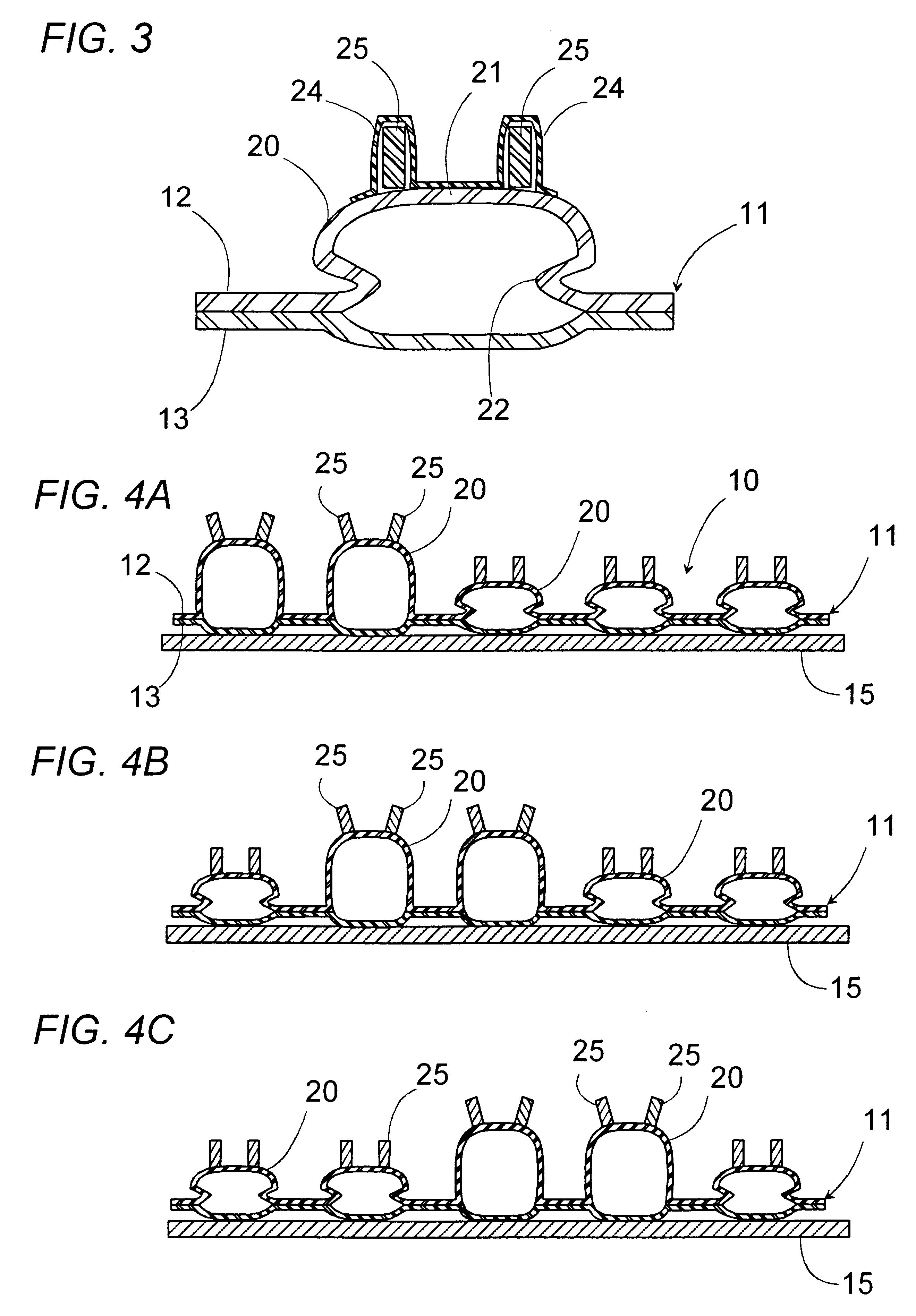
Preferably, each of the bags is formed of a flexible material in its entirety including the top end wall. Each of the applicators is made of a hard material which is inserted into a flexible sheath bonded to the top end wall of each bag. Thus, the applicator can be easily integrated with the bag without requiring any additional intervening supporting mechanism, assuring easy fabrication of the system.
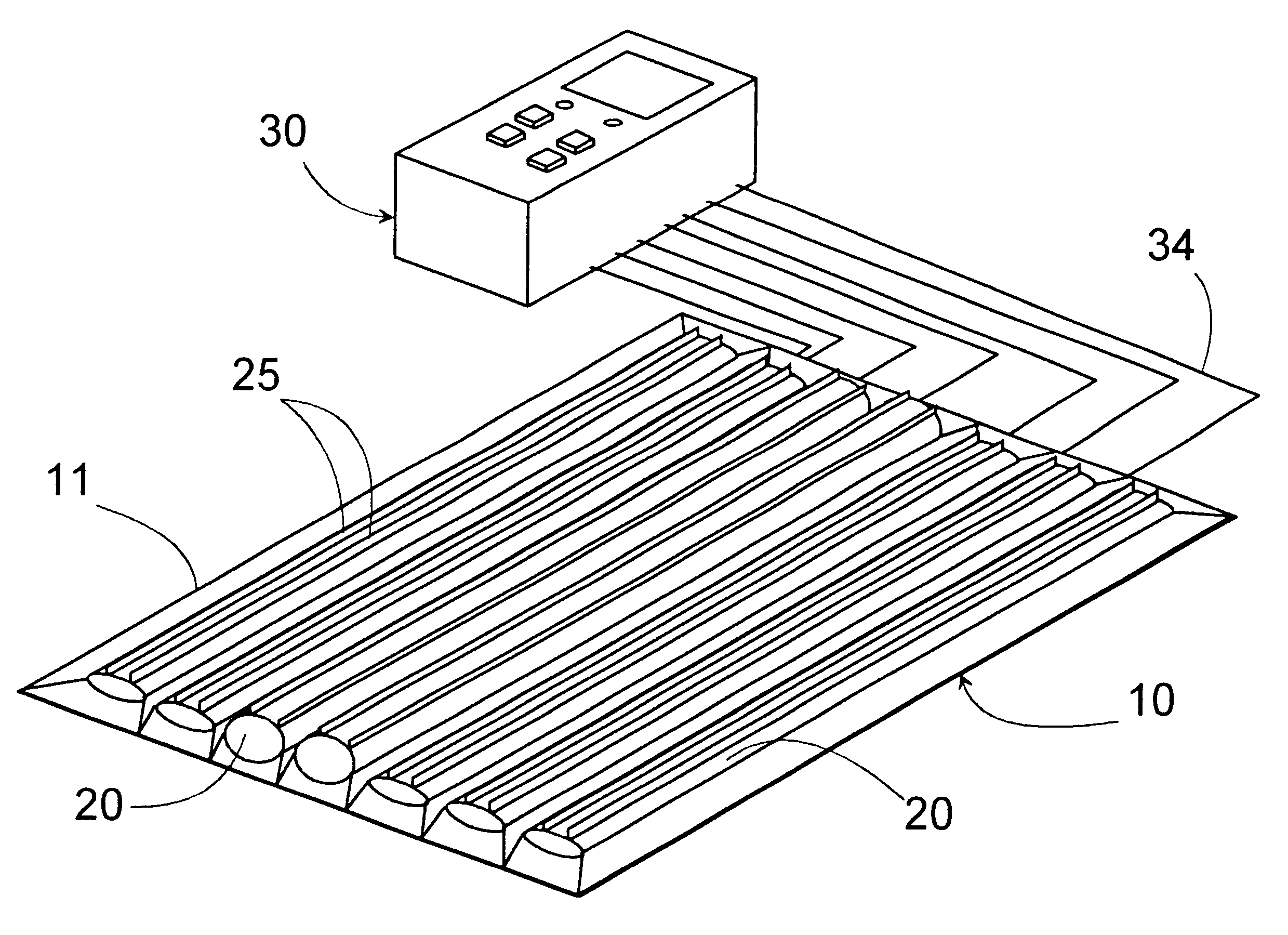
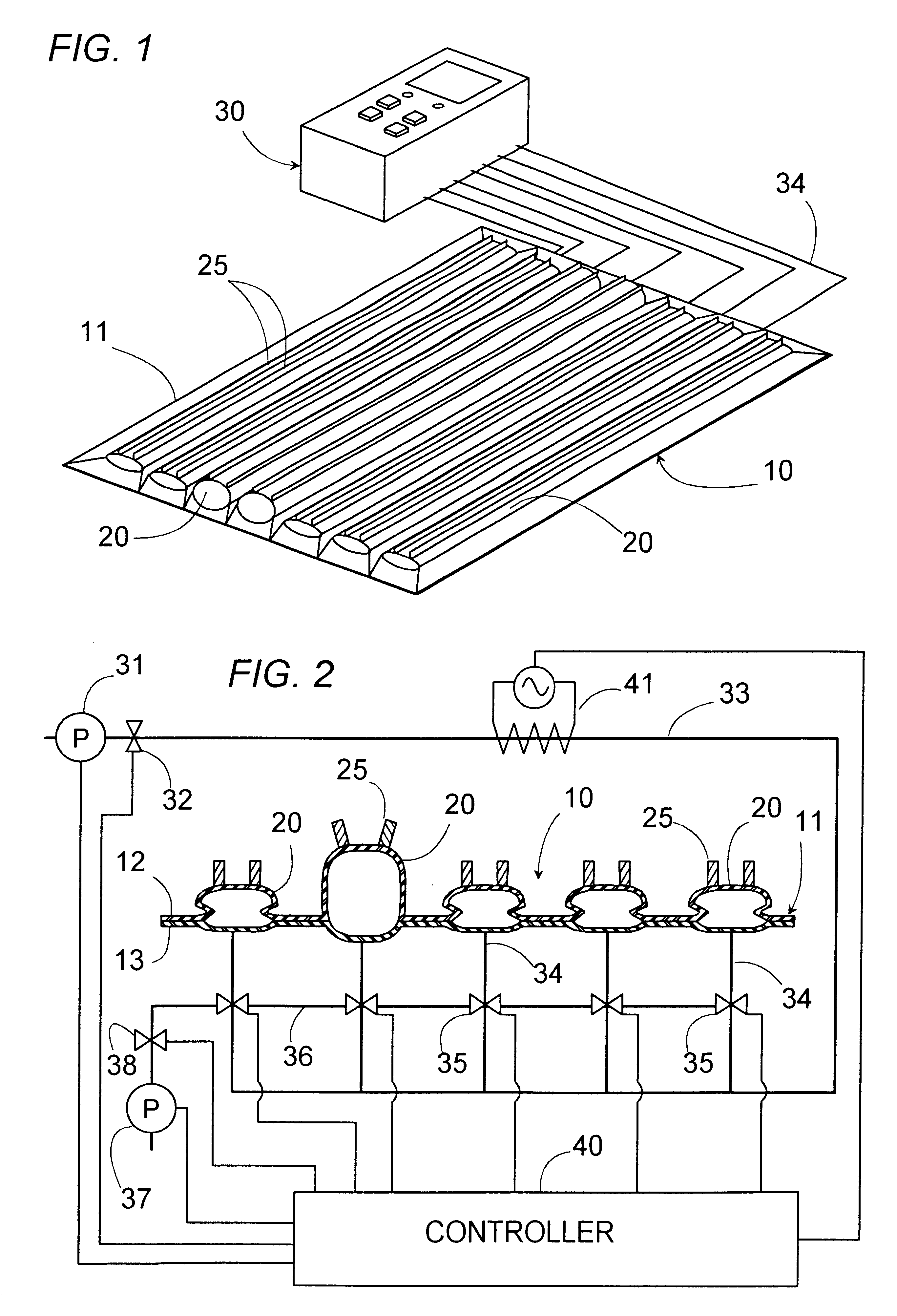
The base sheet may be shaped into a rectangular configuration having a length and a width, and carry the bags which are of elongated configuration extending along the length of the base and are arranged in parallel with each other. The applicator on each of the bags is in the form of an elongated fin extending along a length of the bag, thereby enabling to concentrate the massage action over an extended portion of the user's body at a time.
In this connection, each bag may be provided with a parallel pair of the applicators which are so positioned on the flexible top end wall as to displace distal ends of the applicators away from each other as the bag is caused to inflate. Therefore, the applicators in the pair can act to stretch the portion of the user's body confined between the applicators, thereby realizing a comfortable treatment.
The bag is preferred to have a side wall in the form of a bellows so as to inflate the bag sufficiently without necessitating any substantial elastic deformation of the bag.
The charging and discharging unit responsible for inflating and deflating the bags may be configured to include a charging pump of supplying the pressurized fluid into the individual bags respectively through fluid channels, and a plurality of two-way valves provided respectively in the fluid channels for charging and discharging the pressurized fluid into and from the bags to inflate and deflate the bags. A suction pump is included to be connected to the valves through a common exhaust path for positively discharging the pressurized fluid out of the bags. Thus, the bags can be inflated and deflated at an increased rate to strengthen the massage action applied to the user's body.

Problems solved by technology

However, since the force generated by the inflation of the bag is distributed over substantially the entire surface of the bag, it is difficult to concentrate a relatively large force to a particular portion of a human body, failing to realize a strong massage action.
However, there is required a complicated structure for supporting the applicator on the bag in such a manner as to transmit the inflation of the bag made of the flexible bag to the massaging movement of the applicator made of a hard material.
The use of such supporting mechanism makes it difficult to realize a compact massaging system at a minimum number of components, and particularly to design the massaging system which covers a wide area of the human body, yet which is light-weight and compact sufficient for easy adaptation in a bed, a bed, backrest of the chair, or even in a band placed around a leg or arm of the user.

Method used


Image

  • Massaging system
  • Massaging system
  • Massaging system

Examples


Embodiment Construction

Referring now to FIGS. 1 and 2, there is shown a massaging system in accordance with a first embodiment of the present invention. The system is composed of a massage unit 10 and a control unit 30. The massage unit 10 is provided in the form of a flexible mat which can be mounted on a bed or a backrest of a chair to apply massage treatment to the back of a user's body. The massage unit 10 comprises a base sheet 11 carrying a plurality of expandable bags 20 of elongated configuration arranged in parallel with each other. The base sheet 11 is composed of two layers 12 and 13 of flexible plastic resin material, for example, vinyl chloride resin or soft urethane resin, which are partially heat-welded to define the bags 20 between the unwelded portions of the layers. Each of thus formed bags 20 is provided on its top end wall 21 with a pair of applicators 25 each in the form of a fin extending along the entire length of the bag for contact with a portion of the user's body to apply a mass...


PUM


Abstract

A massaging system includes a base sheet carrying a plurality of expandable bags arranged in a plane of the base sheet, and a charging and discharging unit connected to the bags for selectively supplying and discharging a pressurized fluid into and from the bags so as to inflate and deflate the bags, selectively. At least one applicator projects from each of the bags in contact with a portion of a human body for applying a massaging action. Each bag has a flexible top end capable of deforming into a curved contour when being inflated. The applicator is made of a hard material and projects directly from the top end wall of the bag as an integral part of the bag such that the applicator is caused to displace in a direction different from a direction along which the bag inflates and deflates principally, as a consequence of that the flexible top end wall deforms into the curved contour. Thus, the applicator can concentrate a massaging force resulting from the inflation of the bag to a particular portion of the user's body, giving a relatively strong local massage action sufficient for optimum treatment. Further, since the applicator takes a lateral movement in the direction generally perpendicular to the inflating direction during the inflation of the bag, the applicator can give a rubbing action, in addition to the pressing action, to the user's body for realizing effective and comfortable massage treatment analogous to that made by a human therapeutic massager.

Description

1. Field of the InventionThe present invention is directed to a massaging system, and more particularly to a massaging system utilizing a pressurized fluid to inflate and deflate selective ones of expandable bags arranged in an array for producing a massaging action to a human body.2. Description of the Prior ArtU.S. Pat. No. 4,622,706 discloses a prior massaging system in the form of an air mat which comprises an array of expandable bags. A source of pressurized air is connected to the individual bags for selectively inflating and deflating the bags to give a massaging force applied to a human body lying on the mat. However, since the force generated by the inflation of the bag is distributed over substantially the entire surface of the bag, it is difficult to concentrate a relatively large force to a particular portion of a human body, failing to realize a strong massage action. This problem is somewhat solved in another massaging system as disclosed in U.S. Pat. No. 5,741,218. Th...

Claims


Application Information

Patent Timeline
Patent Type & Authority Patents(United States)
IPC IPC(8): A47C7/46A47C27/10A61H23/04A61H7/00
CPCA47C7/467A47C27/082A47C27/083A47C27/10A61H7/002A61H9/0078A61H2201/165A61H2201/0134A61H2201/0146A61H2201/1623A61H2201/1635A61H2201/164
Inventor DONO, SHIGERUHATA, HITOSHIKITANO, YUKIHIKO
Owner MATSUSHITA ELECTRIC WORKS LTD
Learn More