
Hybrid resist based on photo acid/photo base blending

Inactive Publication Date: 2002-01-15
IBM CORP
View PDF14 Cites 140 Cited by
  • Summary
  • Abstract
  • Description
  • Claims
  • Application Information

AI Technical Summary

Benefits of technology

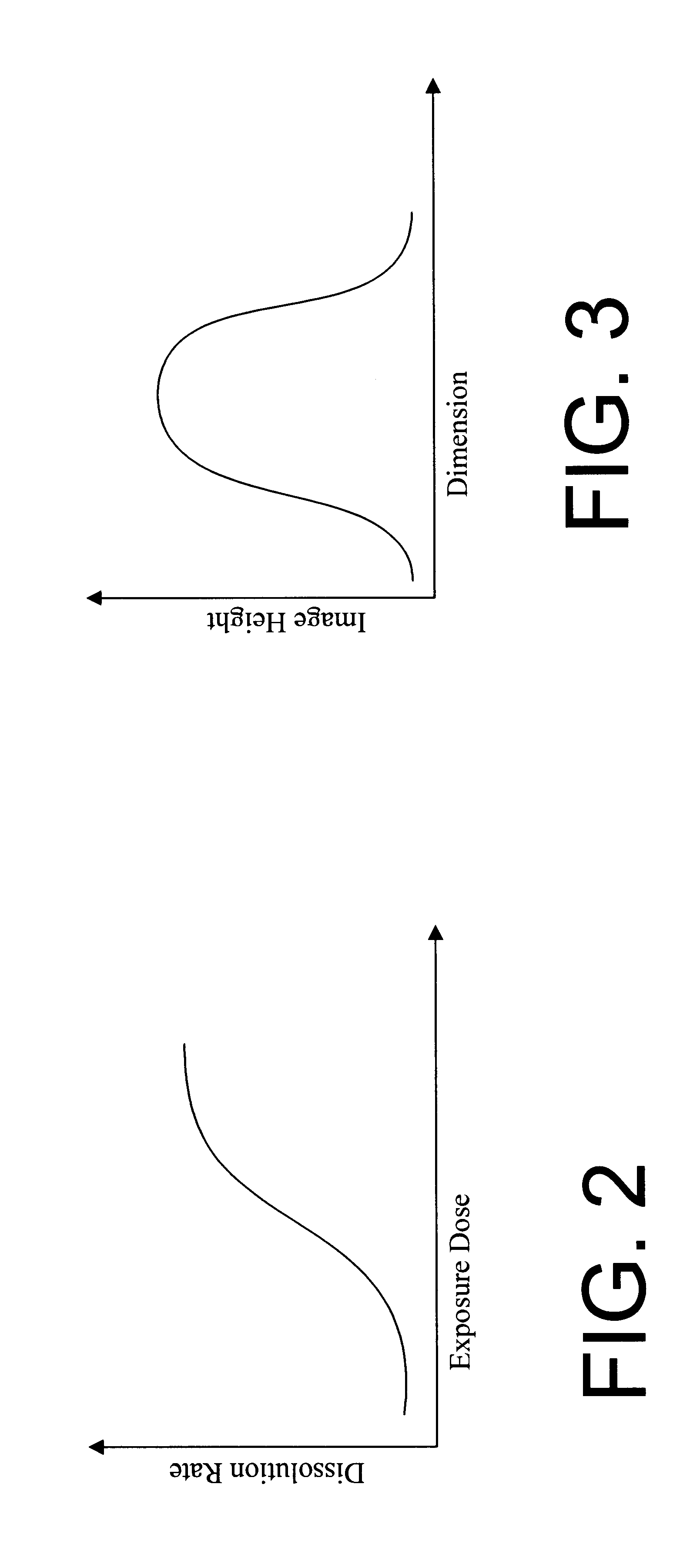
Further, a quenching agent additive may be included in the photo resist composition that shifts the first solubility transition of the dissolution curve caused by the first catalyst toward a second solubility transition of the dissolution curve caused by the photo generated quenching agent. A photo resist exhibiting such a change in the dissolution curve will produce a space or a line in the resist that is reduced in width compared to a corresponding space or line created without the quenching agent additive. Thus, altering the width of features, potentially sub-lithographic features, in a hybrid resist is enabled.

Problems solved by technology

Unfortunately, such enhancements tend to offer only minor increases in density and the limits of optical enhancements appears inevitable in the near future.
Further, in the scaling of lithography, the physical limits of some of the parameters previously relied upon to print smaller features are being approached.
As described in the related applications incorporated by reference above, hybrid resists provide one means of accomplishing this goal, however, existing hybrid photo resist compositions also have limitations.
However, diffraction patterns are formed at to the edges of the reticle, resulting in partial exposure of the resist about the edges of the a reticle.
Current formulations, however, are not capable of printing a sub-lithographic line at the edges of the aerial image.
Nevertheless, the result of this advantage is that it can be difficult to alter the width of a sub-lithographic space in a hybrid resist image.

Method used


Image

  • Hybrid resist based on photo acid/photo base blending
  • Hybrid resist based on photo acid/photo base blending
  • Hybrid resist based on photo acid/photo base blending

Examples


Embodiment Construction

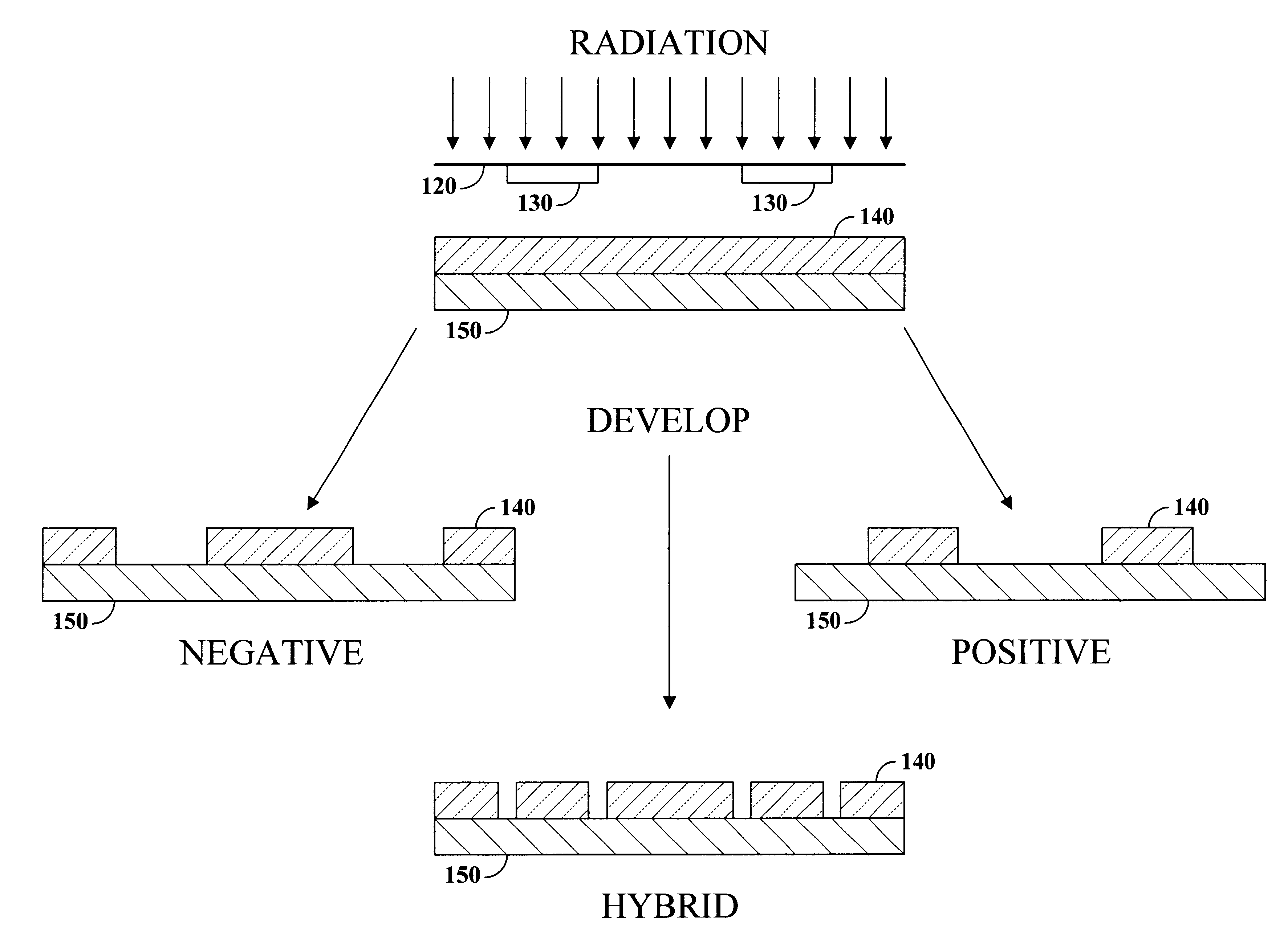
According to a preferred embodiment of the present invention, a photo resist composition is provided containing a polymer resin, a first photo acid generator (PAG) requiring a first dose of actinic energy to generate a photo acid, and a photo base generator (PBG) requiring a second dose of actinic energy, different from the first dose, to generate a photo base. The amounts and types of components in the photo resist are selected to produce a hybrid resist image, including at least one line and at least one space, within an exposed region of the photo resist as the result of a single exposure to actinic energy. Either the photo acid or photo base acts as a catalyst for a chemical transformation in the resist to induce a solubility change. The solubility change is either positive, rendering an initially insoluble resist soluble in developer, or negative, rendering an initially soluble resist insoluble in developer. The other compound is formulated in material type and loading in the r...


PUM


Abstract

A photo resist composition contains a polymer resin, a first photo acid generator (PAG) requiring a first dose of actinic energy to generate a first photo acid, and a photo base generator (PBG) requiring a second dose of actinic energy, different from the first dose, to generate a photo base. The amounts and types of components in the photo resist are selected to produce a hybrid resist image. Either the first photo acid or photo base acts as a catalyst for a chemical transformation in the resist to induce a solubility change. The other compound is formulated in material type and loading in the resist such that it acts as a quenching agent. The catalyst is formed at low doses to induce the solubility change and the quenching agent is formed at higher doses to counterbalance the presence of the catalyst. Accordingly, the same frequency doubling effect of conventional hybrid resist compositions may be obtained, however, either a line or a space may be formed at the edge of an aerial image. Feature size may also be influenced by incorporating a quenching agent into the resist composition that does not require photo generation.

Description

1. Technical FieldThis invention relates generally to the field of semiconductor manufacturing and, more specifically, to photo resist compositions including both photo acid and photo base components that are adapted to produce a hybrid resist image.2. Background ArtThe need to remain cost and performance competitive in the production of semiconductor devices has caused continually increasing device density in integrated circuits. To facilitate the increase in device density, new technologies are constantly needed to allow the feature size of these semiconductor devices to be reduced. For the past 20 years, optical lithography has driven the device density and the industry has resorted to optical enhancements to allow increasing densities. As an example, some such enhancements include over exposing / over developing, hard and soft phase shifts, phase edge masks, and edge shadowing. Unfortunately, such enhancements tend to offer only minor increases in density and the limits of optical...

Claims


Application Information

Patent Timeline
IPC IPC(8): G03F7/004G03F7/095
CPCG03F7/0045G03F7/095Y10S430/115Y10S430/12
Inventor CHEN, KUANG-JUNG R.HAKEY, MARK C.HOLMES, STEVEN J.HUANG, WU-SONGRABIDOUX, PAUL A.
Owner IBM CORP
Learn More