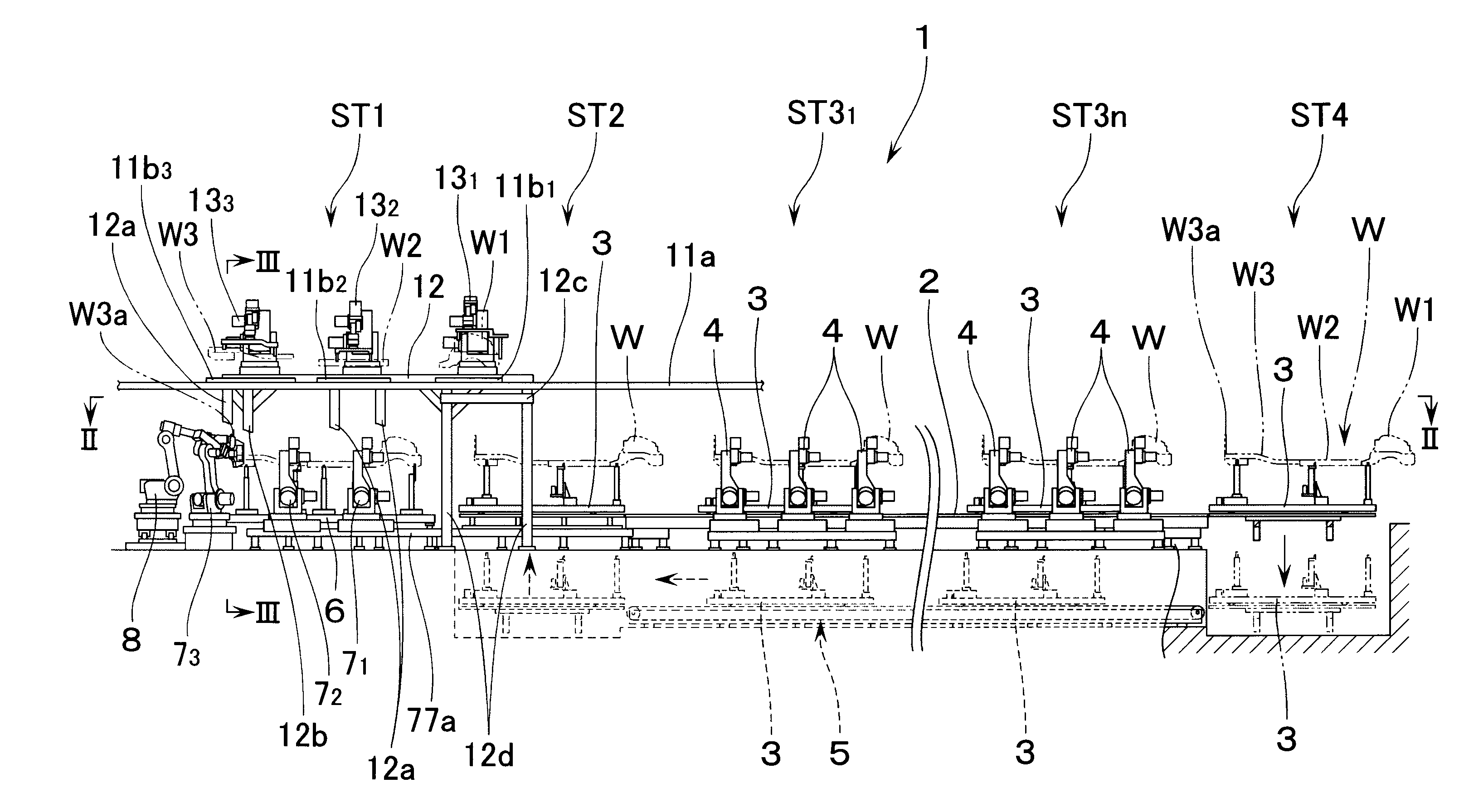
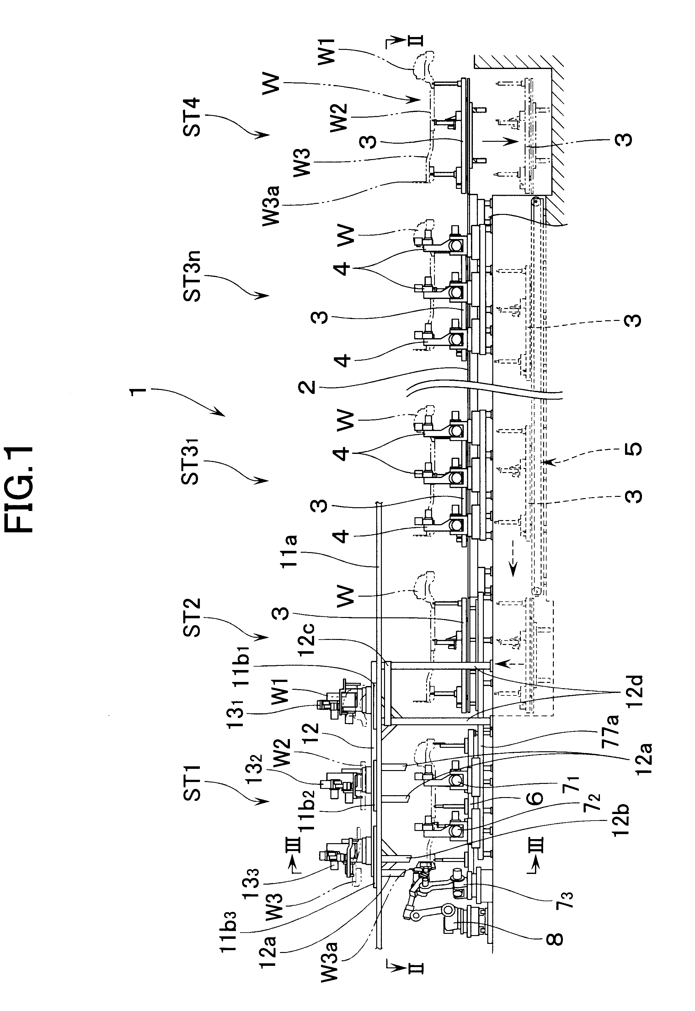
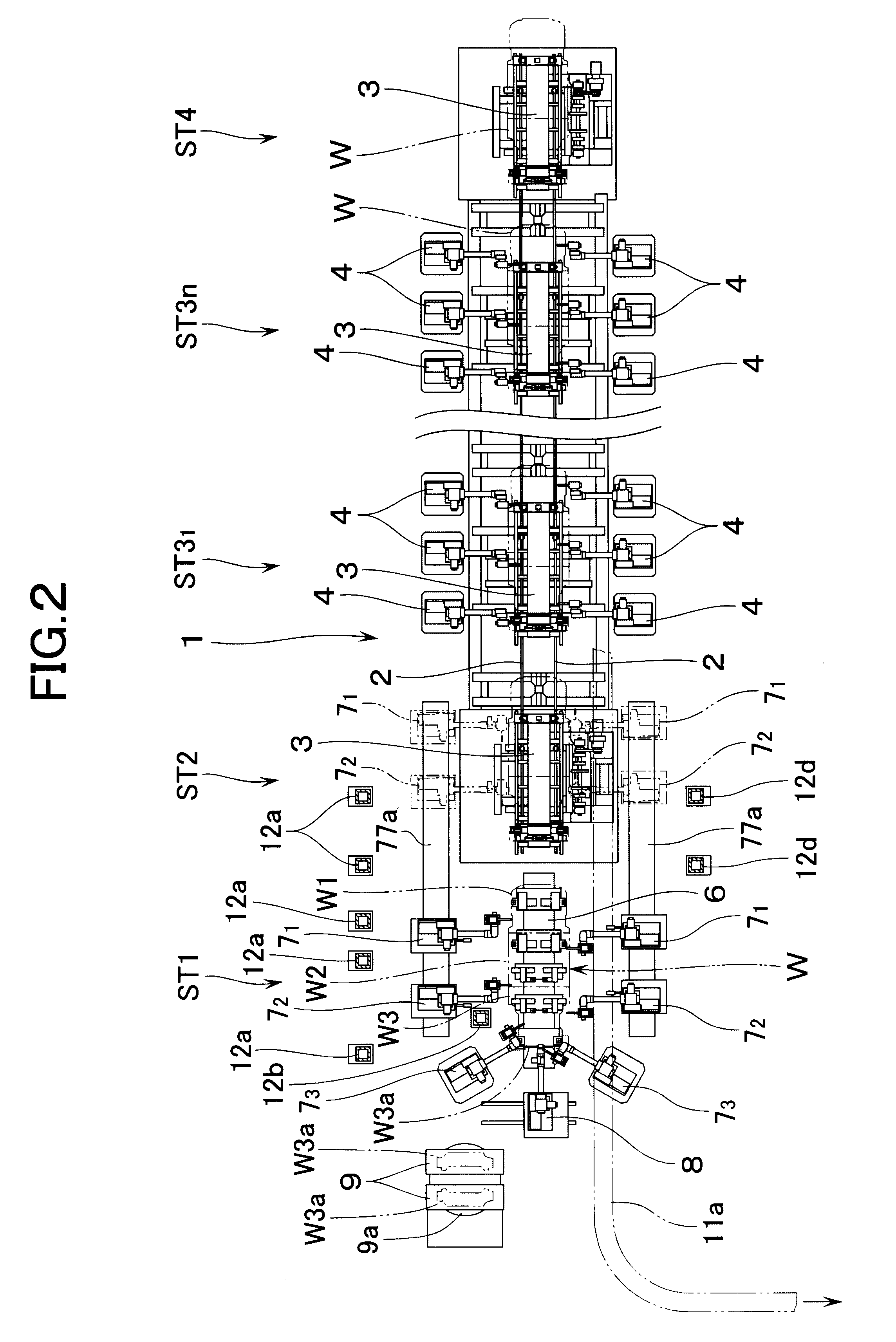
According to the present invention, at least two welding robots on each lateral side of the floor assembly station, i.e., a total of four welding robots, are constituted into dual-purpose welding robots for performing both welding work and transporting work, and the floor is supported through the workpiece receiving member at least at four longitudinal and lateral positions. Therefore, even if the floor is large in size and weight, it can be transported in a stable manner. In addition, since the workpiece receiving members may support only part of the floor, they can be formed small in size. Therefore, even in a state in which the workpiece receiving member remains mounted on the operating end of the robot, the assembly work of the floor can be performed without interference of the workpiece receiving member with the floor. Right after the floor has been assembled, the floor can be supported by the workpiece receiving members and can therefore be quickly transported.
The floor is provided with a jack-up point at each of four longitudinal and lateral positions, the jack-up point being for applying a jack at the time of jacking up the vehicle. Since the jack-up point is high in rigidity, the stability in supporting the floor improves if each of the workpiece receiving members of the dual-purpose welding robots supports each of the jack-up points of the floor. In this case, it is preferable to arrange the workpiece receiving member of at least one of the dual-purpose welding robots to support a corresponding jack-up point by aligning the corresponding jack-up point in both longitudinal and lateral directions, to thereby prevent the floor from deviating in position during transportation.
Preferably, the welding gun is mounted, through a supporting frame, on a
wrist of three-axis construction provided at a front end of a robot arm of each of the dual-purpose welding robots, wherein the supporting frame is made up of: that first side frame on one side which extends in a longitudinal direction at a right angle to an axis of rotation of a
wrist member provided at a front end of the
wrist and which is coupled to the wrist member; a second side frame on a side opposite to, and parallel with, the first side frame; and cross members which combine both the first and second side frames, wherein the welding gun is mounted between the first and second side frames such that a gun arm projects in one longitudinal direction of the first and second side frames, and wherein the workpiece receiving member is fixed to an outer side surface of the second side frame. According to this arrangement, when the floor is supported, the load which operates on the workpiece receiving member is received by the supporting frame. Therefore, the load from the workpiece receiving member does not operate on the welding gun, thereby preventing the welding gun from being adversely affected. In addition, the workpiece receiving member is fixed to that surface of the supporting frame which faces the direction different from the direction in which the gun arm projects. Therefore, the welding work of the workpiece can be performed without interference of the workpiece receiving member with the workpiece. Also, the workpiece can be supported through the workpiece receiving member without interference of the gun arm with the workpiece.
Further, preferably, a position of fixing the workpiece receiving member is set such that, when the floor is supported by the workpiece receiving member, an operation line of a load to operate on the workpiece receiving member coincides with a
vertical plane which includes the axis of rotation of the wrist member. The wrist member can thus be prevented from being subject to a moment of rotation when the workpiece is supported. The stability in supporting the workpiece can advantageously be improved.
When the welding work has been repeated, the
electrode tip (i.e., the front end of the
electrode) of the welding gun will get out of shape. Therefore, it becomes necessary dress (or reform) the electrode tip from time to time. As a conventional method of dressing the electrode tip of a welding robot which performs only the welding work of a workpiece, there is disclosed the following art in Japanese Published Unexamined
Patent Application No. 228678 / 1989. Namely, an electrode tip dressing device is disposed close to a position in which a welding robot is disposed. While the workpiece is being transported after the welding work of the workpiece has been finished, the welding robot is operated such that the electrode tip of the welding gun comes into contact with the electrode tip dressing device, whereby the electrode tip is dressed. However, in that dual-purpose welding robot of the present invention which performs the welding work and the transporting work, the dressing of the electrode tip cannot be performed while the workpiece is being transported. Therefore, a time for electrode tip dressing must be separately reserved, resulting in a hindrance to an attempt to improve the workability. In this case, preferably, the apparatus further comprises travel bases which are provided so as to be reciprocated between the floor assembly station and the subsequent station, each of the dual-purpose welding robots being mounted on each of the travel bases; an electrode tip dressing device which is movable together with each of the travel bases, wherein, when each of the travel bases is moved from the subsequent station back to the floor assembly station, each of the dual-purpose welding robots is operated such that a welding electrode of each of the welding guns contacts each of the electrode tip dressing devices to thereby dress each of the electrode tips. It is thus not necessary to separately reserving a time for electrode tip dressing. The productivity can thus be improved.
In such a case, preferably, the apparatus further comprises: transporting means for transporting three workpieces of a front component, a front floor, and a rear floor which constitute the floor of the vehicle into a workpiece feeding section which is located above one lateral side of the floor assembly station; an overhead frame which is provided above the other lateral side of the floor assembly station; three transfer robots for three workpieces of the front component, the front floor, and the rear floor, disposed on the overhead frame in a longitudinally spaced relationship from one another, each of the transfer robots comprising: a rotary base rotatable about a vertical axial line; a first arm coupled to the rotary base through a first joint; a second arm swingably coupled to a front end of the first arm through a second joint; a wrist of three-axis construction at a front end of the second arm; and a workpiece holding device for holding each of the workpieces attached to the wrist, wherein each of the workpieces transported into the workpiece feeding section: is picked up by each of the transfer robots; is rotated by the movement of the rotary base of each of the transfer robots into a position which lies above a
free space between the workpiece feeding section and the overhead frame; is lowered through the
free space for alignment into a predetermined positional relationship with one another in a position right above the setting jig; and is put in position onto the setting jig. According to this arrangement, a six-axis general-purpose robot can be used as the transfer robot. Therefore, there is no need of constituting the transfer means as an exclusive equipment, resulting in a lower equipment cost. Further, since the transfer robot is disposed on the overhead frame, the movable range of the welding robot to be disposed on the side portion of the floor assembly station can be secured wide enough in the
free space below the overhead frame.


