Composite bicycle frame and method of construction thereof

a bicycle frame and composite technology, applied in the field of metal bicycle frames, can solve the problems of corresponding frame strength loss, inability to manufacture in mass quantities, and inability to use composite tubes and metal lug combinations according to these known processes, so as to avoid the extra weight and strength reduction

Inactive Publication Date: 2002-01-22
RADIUS ENG
View PDF68 Cites 69 Cited by
  • Summary
  • Abstract
  • Description
  • Claims
  • Application Information

AI Technical Summary

Benefits of technology

It is a principal object of the present invention to provide an all composite bicycle frame, wherein the entire frame or three d...

Problems solved by technology

If the metal lugs are reduced in size to reduce weight there must be a corresponding reduction in size of the composite tubes, with corresponding loss of strength of the frame.
Since weight reduction and strength are of primary importance, the use of a combination of composite tubes metal lugs has not been entirely satisfactory.
Frames made according to these known processes are not generally amenable to mass production, primarily due to the amount of manual labor required at each stage of the manufacturing process.
Consequently, the frames are not commercially viable.
These dividing lines of overlapping composites provide weakness areas in the lugs and undesirable increased weight.
Joints between frame members are the most frequent source of structural problems occurring in bicycle frames.
This is because internal structural loads are generally the greatest at the joints, and because it is difficult to bond the different materials at the joints.
While these frames are successful to the large extent, there are many practical concerns, and manufacturing problems relating to the complexity of forming the entire bicycle frame in one step.
However, complex three-...

Method used


Image

  • Composite bicycle frame and method of construction thereof
  • Composite bicycle frame and method of construction thereof
  • Composite bicycle frame and method of construction thereof

Examples


Embodiment Construction

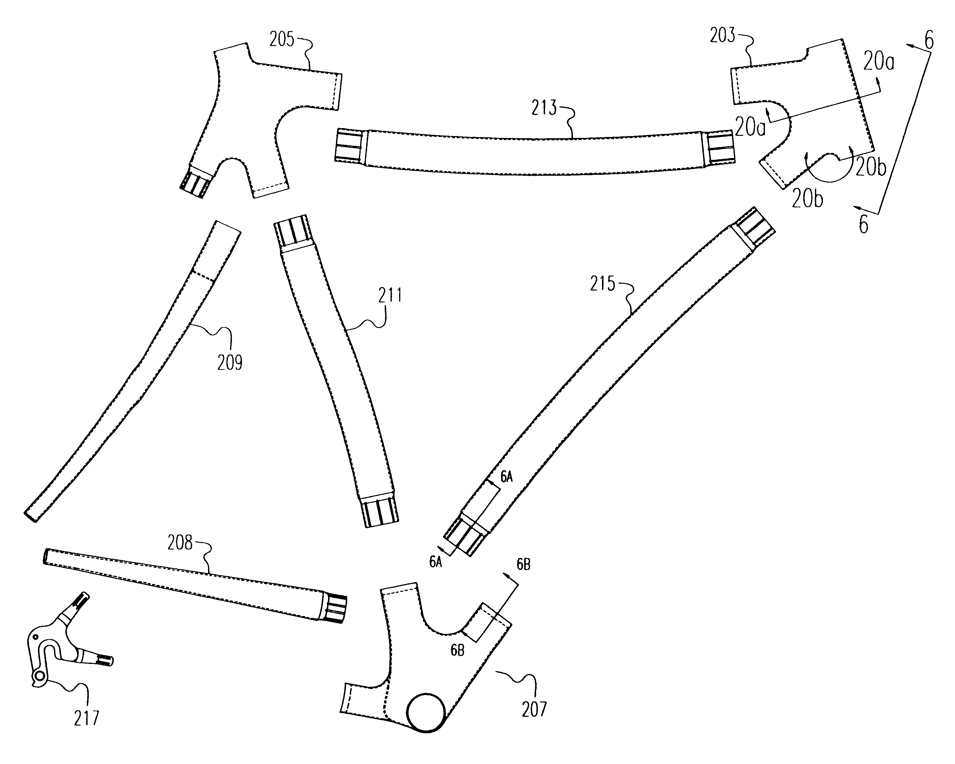
201 jointed or "lugged" tubular bicycle frame

203 head tube lug

205 seat tube lug

207 bottom bracket lug

208 chain stay tube

209 seat stay member

211 seat tube

213 top tube

215 down tube

217 metallic drop out

219 plug on down tube

221 socket in bottom bracket lug to accept down tube plug

225 mandrel core

227 flexible bladder

229 inflation fitting opening in bladder

233 thin film sheets of a thermally vacuum formed bladder

234 thin film sheets of a bladder made from flat film not thermally vacuum formed

235 initial heat seals made on bladder prior to insertion of mandrel core

237 area delimited on bladder for final heat seal after mandrel core / s have been inserted in bladder

238 final heat seal on bladder made on bladder after mandrel core / s have been inserted

239 bladder fitting

239a bladder fitting inner sleeve

239b bladder fitting outer sleeve

241 assembly of mandrel core, bladder and bladder fitting

242 mold set

243 mold bottom half

244 wrapped assembly of mandrel core, bladder and bladder fitting

245 ...


PUM

PropertyMeasurementUnit
Ratioaaaaaaaaaa

Abstract

Bicycle frame components without laps made by a method comprising;shaping a fluid-removable core in the general form of the component,placing a flexible inflatable bladder around the core,wrapping over the assembly of core and bladder at least one ply of fiber impregnated with a curable resin, forming a cured part by inflating the bladder while the assembly of core, bladder, and impregnated fiber is in a mold to force the plies against the inner surfaces of the mold, such that compaction of the fiber against the mold is predominantly from the bladder inflation and not from the core, and heating to cure the resin to form a cured part, removing the bladder and the fluid-removable core from the interior of the cured part by disintegrating the fluid-removable core with a fluid sufficient to allow removal of the core and the bladder.

Description

(Not applicable)This invention relates to bicycle frames. It is particularly related to light weight, very strong bicycle frames made of composite materials.Discussion of Prior Art.Traditional Metal Bicycle FrameBicycle frames have traditionally been constructed of assembled metal tubes. A variety of methods have been used to connect the metal tubes. The most common methods have included welding, soldering or brazing. It has also been common to use preformed metal lugs as connectors at the junctions of the metal tubes. The preformed lugs reinforce, or add strength and stiffness to the welded, soldered, or brazed joint.Bicycle Frames Utilizing Advanced Composite TubesSome modern bicycle frames utilize composite materials to increase the strength and stiffness of the frames, while reducing frame weight, relative to traditional metal frames. Composite materials have a lower density, higher specific strength and stiffness, and better damping qualities than traditionally used metals. The...

Claims


Application Information

Patent Timeline
IPC IPC(8): B29C33/52B29C33/40B29C70/04B29C70/44A63B53/04B62K19/16
CPCB29C33/40B29C33/52B29C43/18B29C70/44B62K19/16B29C70/446A63B53/04A63B2209/023Y10T428/1321B29L2031/3091B29L2031/5227Y10T428/1362Y10T428/1393
Inventor NELSON, RONALD H.MILOVICH, DIMITRIJECLARK, PAUL NORDSTROMLOUGHRY, GREGORY JOSEPH
Owner RADIUS ENG
Why Eureka
Try Eureka