
Anamorphic object optimized function application for printer defect pre-compensation

Inactive Publication Date: 2002-01-22
XEROX CORP
View PDF26 Cites 55 Cited by
  • Summary
  • Abstract
  • Description
  • Claims
  • Application Information

AI Technical Summary

Benefits of technology

One object of the present invention is to provide a method for predicting when a printing problem is likely to occur based on adjacent colors and / or object attributes such as rendering intent, size, or extent in scan or process directions.
Another object of the present invention is to provide a method for correcting / pre-compensating for a predicted printing problem which can apply a different solution in the process direction (down the page) or the scan direction (across the page), in order to better address the majority of printing problems which are asymmetric (different in the scan and process directions).
Another object of the present invention is to provide a method for correcting / pre-compensating for a predicted printing problem which can effect a change not only in the color near an edge but in its attributes such as rendering intent as well. This allows an edge with two different rendering intents (resulting, for example, in different halftones being applied) to be detected and corrected if necessary even if the edge colors are deemed to be compatible.
Another object of the present invention is to provide a method for correcting / pre-compensating for a predicted printing problem which can apply a function to the region near an edge to change its attributes (color, rendering intent, etc.) as a function of the distance from the edge. This allows a wider range of printing problems to be corrected that cannot be solved with a prior art frame or trap.
By applying such a function to the pixels near an edge, a zone can be created around an edge which effectively blocks or masks a variety of potential printing problems to increase overall image quality.

Problems solved by technology

In practice, every color printing system has characteristic defects which can cause subtle problems that detract from achieving the highest possible quality color printing.
For example, ink jet printing must handle excessive ink coverage which can cause bleeding or spreading of colors and paper distortion.
Xerographic printing contends with a different set of problems which can detract from print quality.
Examples are "haloing", in which toner in one separation interferes with toner transfer at the same location in another separation, "tenting", which is toner deletion caused by high toner pile casting a mechanical or electrostatic "shadow" which prevents correct development of abutting toner, trail-edge deletion and starvation, which cause toner deletion at certain edges, or misregistration between two colors.
Many of these characteristic problems in printing systems can be traced to undesirable interactions between abutting colors on the page.
While increasingly sophisticated controls have been added to printing mechanisms to reduce defects and come closer to the perfect printer expected by the digital image, electro-mechanical defects in any printing system are still common and are to be expected at both the low end where system cost restraints preclude use of expensive controls and the high-end where production speeds challenge existing control systems.
For example, large uniform color fills can contain visible mottle in what should be smooth color, because the random noise of the print mechanism causes tiny variations in the amount of color put on the page.
The second (trapping) grouping of prior art is more limited in scope in that it attempts only to pre-compensate for a single printer defect caused by adjacent colors: misregistration.
If a printer misregisters between separations, an thin unwanted white or color line occurs when certain adjoining colors don't abut perfectly.
Instead, this group of prior art simply looks at the edge between two color areas, attempting to predict when two abutting colors could cause a thin line problem if the printing system misregisters.
Instead, it looks for problematic adjacent objects (fills, text, sweeps, images, etc.), with predicted problems caused not only by colliding colors but also colliding attributes such as rendering intent (e.g., two different halftones adjacent to each other) or size in each direction (e.g., some printing problems only occur with objects greater than a certain size in a certain direction).
Even misregistration, the focus adjacency problem of the prior art, generally is more severe in one direction than the other because misalignment along the scan is caused by different mechanisms than misalignment down the page.
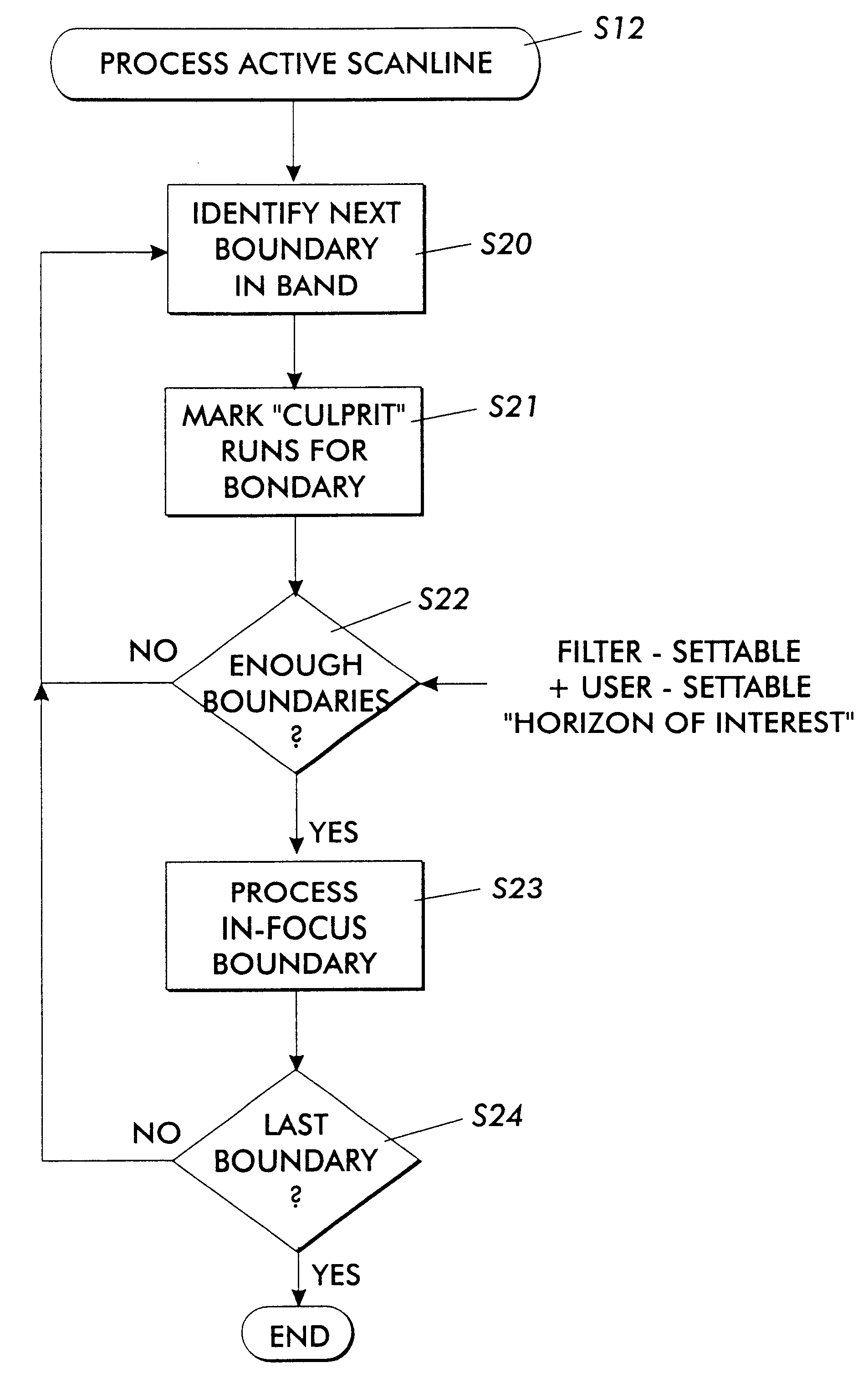
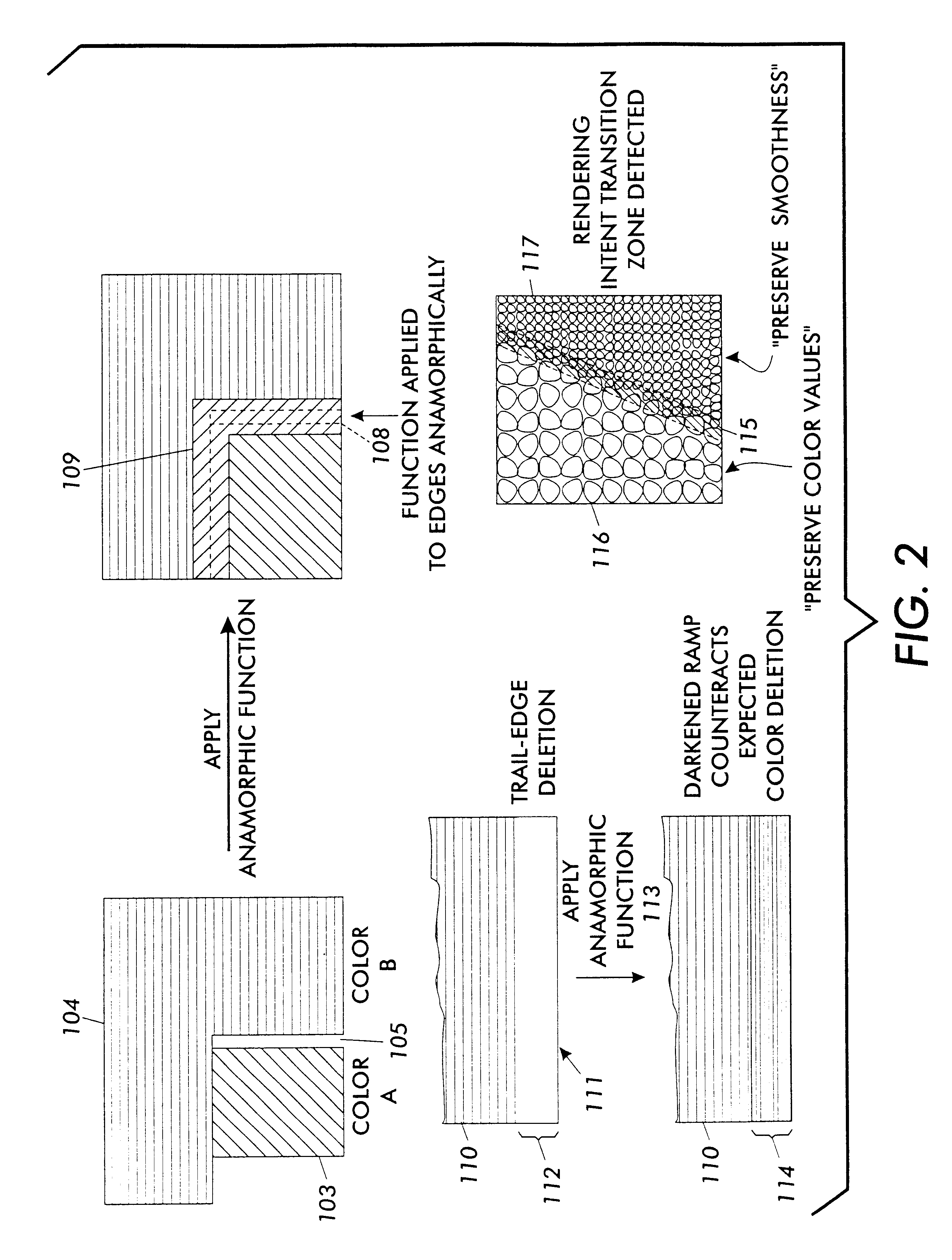
Fourth, in attempting to correct a predicted printing problem, the invention goes beyond the prior art in that it does not simply add a uniform-width, constant-color frame at an edge. Instead, it applies a function to the region near an edge which can change any of its attributes (color, rendering intent, etc.) as a function of the distance from the edge. This is important because it allows the system to solve more effectively a wider range of printing problems. For example, a xerographic printing problem called trail-edge deletion can occur when a color fill with sufficient size in the process direction is printed. At the lower process-direction edge, the toner is often depleted, resulting in a lighter color at the edge. This printing problem cannot be solved with a prior art frame or trap. However, by applying a function which changes the density of the color near the edge as a function of the scanline distance from the edge, the problem may be successfully pre-compensated for by the current invention. Note that the function is anamorphic: only process direction edges are modified. Even with the problem of misregistration, applying a function anamorphically to an edge can allow a subtler solution which might be seen as having the effect of a non-constant color, variable width frame different for each process or scan direction run of color, something not suggested by the prior art.

Method used


Image

  • Anamorphic object optimized function application for printer defect pre-compensation
  • Anamorphic object optimized function application for printer defect pre-compensation
  • Anamorphic object optimized function application for printer defect pre-compensation

Examples


Embodiment Construction

The following notation will be used below to designate the two important directions in printing. The letter "S" will be used to designate the Scan direction (the direction of the scanlines); that is, the direction the laser beam or ink jet Scans across a page. The letter "P" will be used to designate the Process direction (the direction orthogonal to S); that is, the direction the printing Process moves down the page as the laser scans each succeeding line.

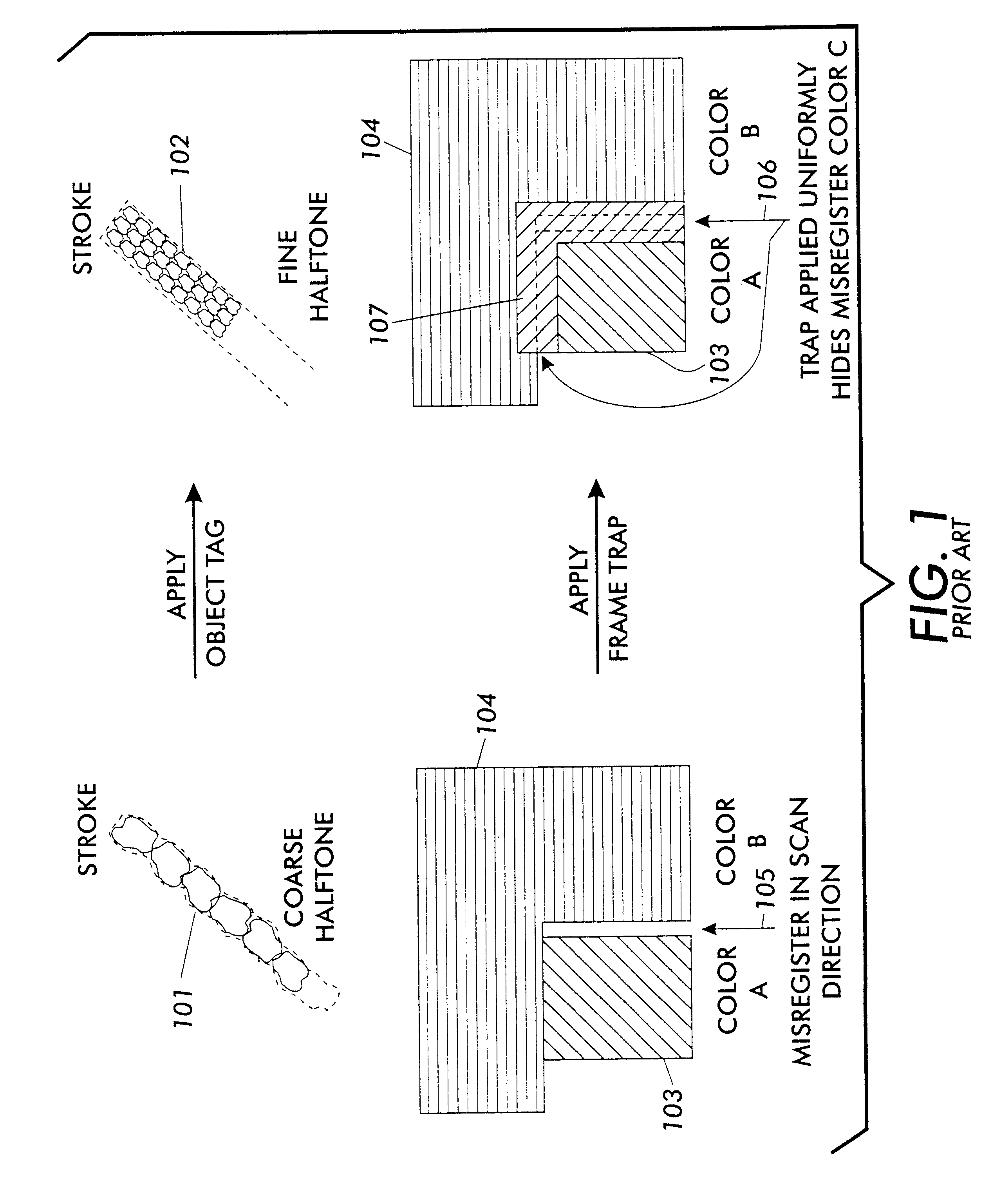
FIG. 1 shows two examples of the types of printing problems currently addressed by the prior art.

First shown is a stroke 101, which looks ragged when rendered with a normal coarse halftone. If the stroke is detected with its object tag, and is rendered instead with a fine halftone, the edges are much sharper as shown by stroke 102. The rendering intent associated with the object type "stroke" generally would indicate that it is more important to preserve edge sharpness than to maintain color fidelity. Thus, a halftone is chosen wh...


PUM


Abstract

Every printing system has characteristic defects which detract from high quality printing. Xerographic printing systems show defects such as banding, mottled colors in large fill areas, trail-edge deletion and starvation where toner concentrations drop at certain color edges, misregistration, and so on. Ink jet printing systems can show ink bleeding, streaking in the direction of head movement, and so on. One approach to reducing printer defects is to refine the electro-mechanics for more precise printing. Another approach which works for predictable defects is to modify the digital data being sent to the printer to pre-compensate for the defect. The prior art does this to a limited extent for individual object types (strokes, fills, images, text, etc.) and for misregistered color edges (trapping). This invention extends the range of edge-related defects that can be both predicted and pre-compensated for. An embodiment of the invention is described which pre-compensates for defects such as trail-edge deletion, starvation, misregistration, halo, etc. by identifying runs of color which meet the criteria likely to cause the effect and applying a function f(edge-distance, object-type) to such runs to modify them appropriately. Both the prediction criteria and the functions applied are anamorphic (the scan direction and process direction are treated differently) and object-optimized (object attributes are taken into account). Further, both prediction criteria and applied correction functions allow user-settable input.

Description

1. Field of the InventionThe present invention relates to high-quality digital printing in which objects are intermixedly printed, and more particularly, in which a printing process exhibits characteristic, statistically predictable defects which degrade quality. A system-specific and defect-specific function is applied to the digital signal anamorphically (different in the scan and process directions) to change the color or other attributes as a function of distance from an edge to pre-compensate for a defect and thereby increase quality.2. Description of the Related ArtDigital color printers form a digital image for each of several separations, such as cyan, magenta, yellow, and black. The digital image instructs the printing mechanism of the printer in the amount of each color ink to deposit and the method of deposition at each addressable point on the page.A digitally imaged page can consist of graphical objects such as text, lines, fills, pictures, etc, all imaged in ways which...

Claims


Application Information

Patent Timeline
IPC IPC(8): G06T5/00G06K15/02H04N1/58H04N1/56
CPCG06K15/02H04N1/58G06K2215/0085
Inventor RUMPH, DAVID E.NICKELL, ERIC S.COLEMAN, ROBERT M.
Owner XEROX CORP
Learn More