
Polysilicon thin film transistor and method of manufacturing the same

a thin film transistor and polysilicon technology, applied in the direction of transistors, electrical devices, semiconductor devices, etc., can solve the problems of long processing time, disadvantageous small and very small grain size of polycrystalline silicon layer 10

Inactive Publication Date: 2002-01-29
LG DISPLAY CO LTD
View PDF31 Cites 34 Cited by
  • Summary
  • Abstract
  • Description
  • Claims
  • Application Information

AI Technical Summary

Problems solved by technology

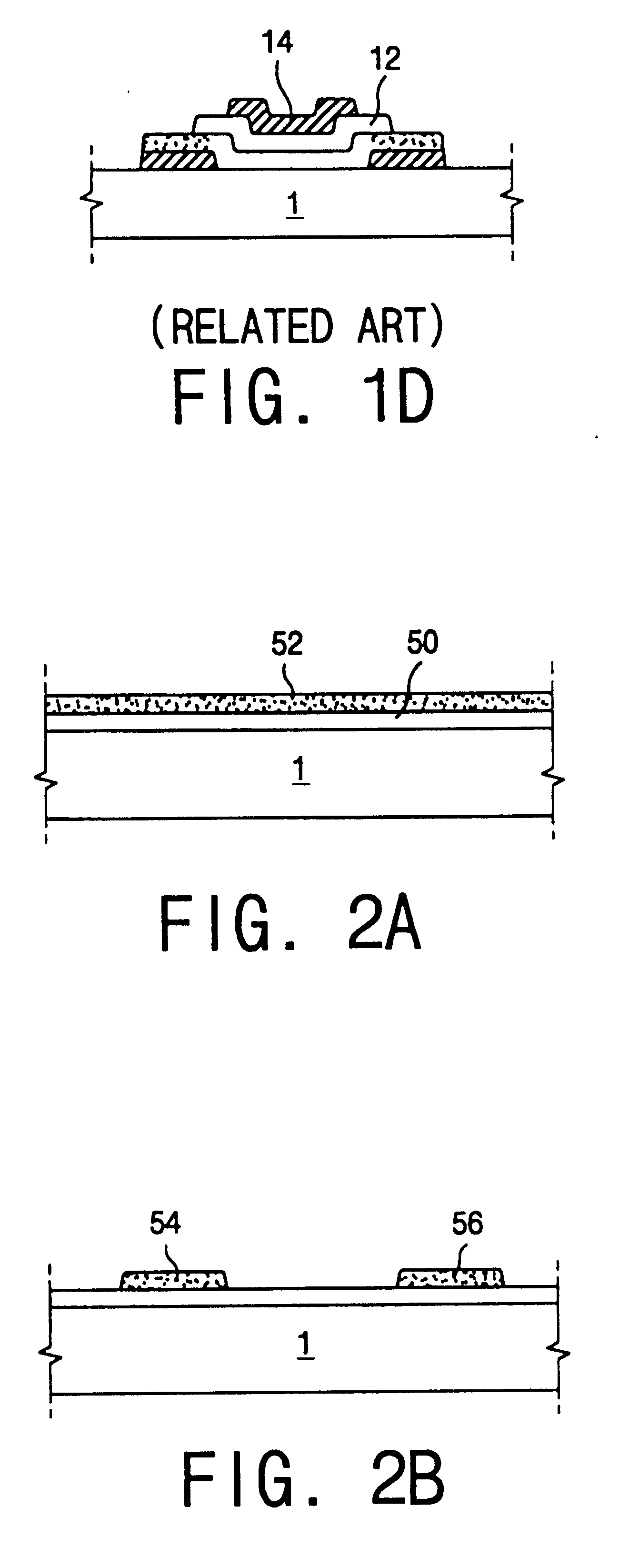
However, there is a problem in that the required energy density causes grains of the polycrystalline silicon layer 10 to be very small.
However, as described above, grains of the polycrystalline silicon layer are disadvantageously small in size.
Further, in the case of using the MIC technique for crystallization, there is a disadvantage in that the processing time is lengthy.

Method used


Image

  • Polysilicon thin film transistor and method of manufacturing the same
  • Polysilicon thin film transistor and method of manufacturing the same
  • Polysilicon thin film transistor and method of manufacturing the same

Examples


first embodiment

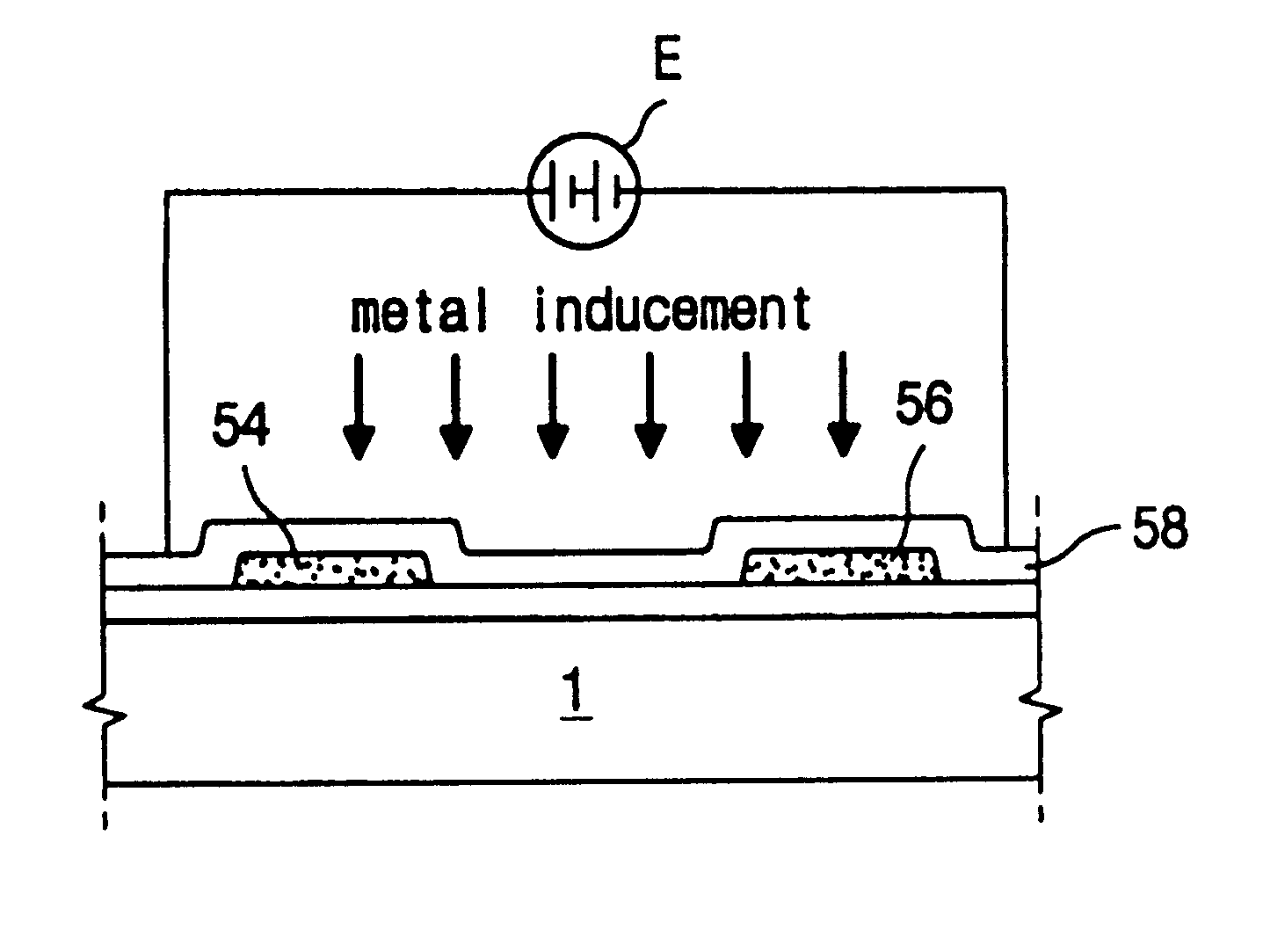
FIGS. 2A to 2F are cross-sectional views illustrating a process of manufacturing a stagger type Poly-Si TFT according to the present invention. As shown in FIG. 2A, a buffer layer 50 is formed on a substrate 1 to prevent extraction of alkali material contained in the substrate 1. Doped amorphous silicon layer 52 with a p-type impurity such as PH.sub.3 or an n-type impurity such as B.sub.2 H.sub.6 is then deposited on the buffer layer 50 and patterned into source and drain regions 54 and 56 (see FIG. 2B). Sequentially, as shown in FIG. 2C, an intrinsic amorphous silicon layer 58 is deposited on the source and drain regions 54 and 56 while covering the entire substrate 1. Then, a metal layer (not shown) is formed on the intrinsic amorphous silicon layer 58 using a sputter technique, a vacuum evaporator technique, or by spin coating technique. The metal layer is made of a material selected from a group consisting of Ni, Pb, and Co.

Alternatively, the metal layer (not shown) may be depos...

second embodiment

the present invention is also intended to prevent short channel effect and, to achieve this, a Lightly-Doped-Drain (LDD) structure or an offset structure is proposed. The short channel effect is also referred to as a hot carrier effect.

FIGS. 3A to 3C are cross-sectional views illustrating process steps to be conducted subsequent to the process shown in FIG. 2C. As shown in FIG. 3A, the polycrystalline silicon layer 58 is patterned to form the active layer 58' such that both its end portions overlap the source and drain regions 54' and 56', respectively. Then, a gate insulating layer 59 and a gate electrode 60 are formed on the active layer 58', spaced a distance of .DELTA.L from the source and drain regions 54' and 56'.

In alternative embodiments, an ion-doping process may be performed to form the LDD structure, or the ion-doping process may be omitted to form the offset structure.

For the LDD structure, ion doping using a gas including one of a boron group such as B.sub.2 H.sub.6 or ...


PUM


Abstract

The present invention discloses a method of manufacturing a polycrystalline silicon thin film transistor including forming a buffer layer on a substrate; depositing an impurity-doped amorphous silicon layer on the buffer layer and patterning the impurity-doped amorphous silicon layer into source and drain regions, where the source and drain regions are spaced apart from each other; forming a metal layer over the entire substrate while covering the source and drain regions; depositing an intrinsic amorphous silicon layer on the metal layer; applying a voltage to the intrinsic amorphous silicon layer to simultaneously crystallize the intrinsic amorphous silicon layer and the source and drain regions so that the intrinsic amorphous silicon layer is converted into a polycrystalline silicon layer; and patterning the polycrystalline silicon layer to form an active layer so that part of the polycrystalline silicon layer overlaps the source and drain regions.

Description

CROSS REFERENCEThis application claims the benefit of Korean Patent Application No. 1999-18387, filed on May 20, 1999, under 35 U.S.C. .sctn. 119, the entirety of which is hereby incorporated by reference.1. Field of the InventionThe present invention relates to a thin film transistor (TFT), and more particularly, to a stagger type polycrystalline silicon thin film transistor (Poly-Si TFT) and a method of manufacturing the same.2. Description of Related ArtIn order to form a polycrystalline silicon layer as an active layer of a TFT, an intrinsic amorphous silicon layer is first deposited on a substrate using a plasma chemical vapor deposition (PCVD) technique or a low pressure chemical vapor deposition (LPCVD) technique so that an amorphous silicon layer is formed. Second, the amorphous silicon layer is crystallized through one of several processes that may include a laser annealing technique, a solid phase crystallization (SPC) technique, and a metal induced crystallization (MIC) t...

Claims


Application Information

Patent Timeline
IPC IPC(8): H01L21/02H01L21/336H01L29/66H01L29/786
CPCH01L29/66757H01L29/78621H01L29/78603H01L29/786
Inventor SEO, SEONG MOH
Owner LG DISPLAY CO LTD
Learn More