Full-bridge DC-to-DC converter having an unipolar gate drive

a technology of unipolar gate drive and dc-to-dc converter, which is applied in the direction of dc-dc conversion, power conversion system, oscillation generator, etc., can solve the problems of increased switching loss, reduced load, and reduced efficiency

Inactive Publication Date: 2002-02-05
IBM CORP
View PDF9 Cites 73 Cited by
  • Summary
  • Abstract
  • Description
  • Claims
  • Application Information

AI Technical Summary

Problems solved by technology

This results in increased switching losses with reduced loads, lower efficiency, and higher electromagnetic influence (EMI).

Method used


Image

  • Full-bridge DC-to-DC converter having an unipolar gate drive
  • Full-bridge DC-to-DC converter having an unipolar gate drive
  • Full-bridge DC-to-DC converter having an unipolar gate drive

Examples


Embodiment Construction

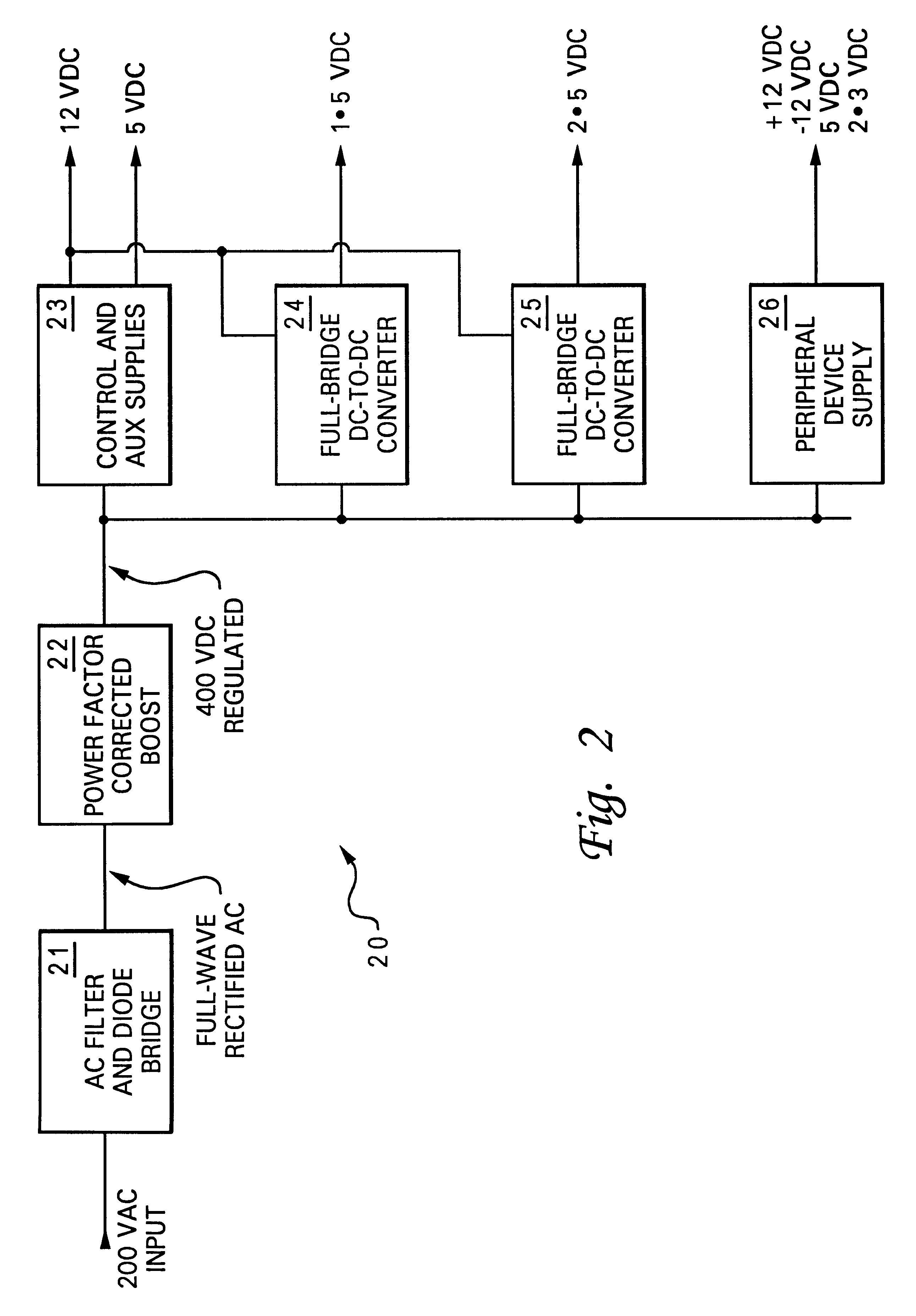
With reference now to FIG. 2, there is illustrated a block diagram of a computer power supply in which a preferred embodiment of the present invention is incorporated. As shown, a computer power supply 20 includes an alternate current (AC) filter and diode bridge 21 to convert a, for example, 200 VAC input to a full-wave rectified AC. A power factor corrected (PFC) boost 22 then converts the full-wave rectified AC to a, for example, 400 V regulated direct current (DC). The regulated 400 VDC is then distributed to various power supplies and regulators, as needed. In FIG. 2, the regulated 400 VDC is distributed to control and auxiliary supplies 23 for providing a 12 VAC and a 5 VDC, to a full-bridge DC-to-DC converter 24 for providing a 1.5 VDC, to a full-bridge DC-to-DC converter 25 for providing a 2.5 VDC, and to a peripheral M device supply 26 for providing a .+-.12 VDC, a 5 VDC, and a 3.3 VDC.

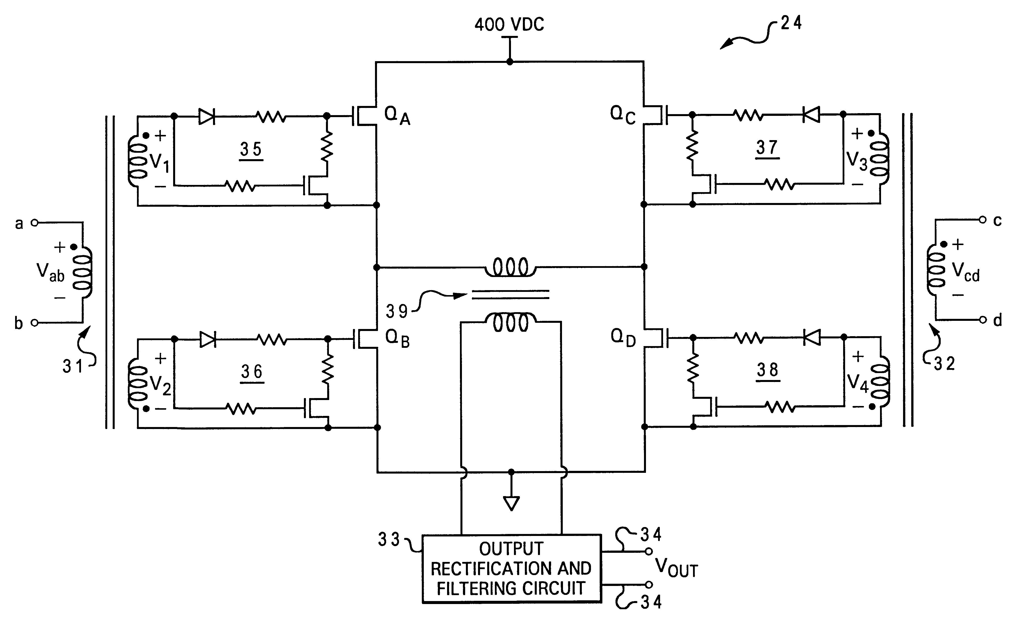
Referring now to FIG. 3, there is illustrated a circuit diagram of a full-bridge DC-to-DC...


PUM


Abstract

A full-bridge DC-to-DC converter having an unipolar gate drive is disclosed. The full-bridge DC-to-DC converter includes a primary-to-secondary transformer, multiple gate drive circuits, and multiple gate drive transformers. The primary-to-secondary transformer converts a first DC voltage to a second DC voltage under the control of the gate drive circuits. Each of the gate drive circuits includes a first transistor and a second transistor. The gate of the first transistor is connected to a pulse voltage source via a diode. The drain of the second transistor is connected to the source of the first transistor, and the source of the second transistor is connected to the gate of the first transistor via a resistor, for discharging a gate-to-source voltage of the first transistor during the time when a voltage of the pulse voltage source is below a gate-to-source threshold voltage of the first transistor. Coupled to at least two of the gate drive circuits, each of the gate drive transformers controls at least two gate drive circuits.

Description

1. Technical FieldThe present invention relates to DC-to-DC converters in general, and in particular to full-bridge DC-to-DC converters. Still more particularly, the present invention relates to a full-bridge DC-to-DC converter having an unipolar gate drive.2. Description of the Prior ArtA direct current (DC) voltage can be converted to another DC voltage via a DC-to-DC converter. The basic topology of a DC-to-DC converter may take a variety of forms, such as a full-bridge inverter, a half-bridge inverter, a buck converter, a boost converter, or a flyback converter. Each topology is better suited for a specific type of application. For example, a boost converter topology is typically used when the desired output DC voltage needs to be greater than the input voltage, while a buck converter topology is typically used when the output voltage needs to be less than the input voltage. Generally, for low-power applications, i.e., below 50 watts, the buck, boost, or flyback converter topolo...

Claims


Application Information

Patent Timeline
Patent Type & Authority Patents(United States)
IPC IPC(8): H02M3/337H03K17/689H02M3/24H03K17/691H03K17/687
CPCH02M3/337H02M1/08H03K17/691H03K17/6871H02M3/33573
Inventor DAUN-LINDBERG, TIMOTHY CHARLESMILLER, MICHAEL LEE
Owner IBM CORP
Why Eureka
Try Eureka