Method and a device for evaluating the integrity of the nuclear fuel in a nuclear plant

a nuclear plant and integrity technology, applied in nuclear monitoring, nuclear energy generation, climate sustainability, etc., can solve the problems of brittle cladding tube, primary defect may develop to a larger defect, and defect appears on the cladding tub

Inactive Publication Date: 2002-02-05
WESTINGHOUSE ATOM
View PDF13 Cites 15 Cited by
  • Summary
  • Abstract
  • Description
  • Claims
  • Application Information

AI Technical Summary

Benefits of technology

sixth means arranged to enable the estimating of the integrity of the fuel based on said analysis. By such a device, it is possible to determine a fuel defect in a very reliable manner and by an at least reduced need of a subjective, individual-related judgement.

Problems solved by technology

During operation it sometimes happens that a defect appears on a cladding tube.
However, after a period of time a primary defect may develop to a larger defect, a so-called secondary defect, which is more serious and consists of a larger hole or a crack extending axially along or essentially perpendicular to the longitudinal direction of the cladding tube.
Such a secondary defect may arise by the penetration of water and steam into the fuel rod at the primary defect and by water and steam penetrating into the fuel rod at the primary defect and, by hydration, making the cladding tube brittle which after a certain period of time cracks during thermal or mechanical load or due to tensions caused by the hydrides themselves.
In case of a really serious fuel defect, for instance due to the fact that a fuel cladding tube is broken, also uranium and plutonium may start to leak out into the core.
The defects on the cladding tubes may have many different grounds.
In case of a too fast effect increase in the fuel, a combination of tension, due to the thermal extension, and chemical influence on the inner side of the cladding tube may result in the cracking of the cladding tube.
Experience has shown that for instance in connection with repair and service of a nuclear reactor, such debris may be introduced and thereafter be carried by the water circulating through the core and give rise to a wear defect in the form of a primary defect on the cladding tube.
A further type of defect may depend on a manufacturing failure.
This leads to a quick local temperature increase in the fuel rod.
Such a temperature increase leads to the melting of the cladding tube if the operation of the reactor is not immediately interrupted.
If, for instance, the reactor is operated with a high effect or if many control rod movements are performed in the proximity of a defect, the defect may develop faster than it would have done at a lower reactor effect or if the control rods would have been maintained in a position.
These questions are very difficult to answer in a secure and reliable manner by the technique available today.
Another problem in this connection is the determination if the primary defect has developed to a secondary defect or if a further primary defect has occurred in the case that higher activity levels of the reactor off-gases have been measured.
One problem in this connection is that there are two different sources of radioactive inert gases, partly from the fuel due to a defect on the cladding tube and partly due to core contamination, i.e. from fissionable compounds being deposited onto different surfaces in the reactor core.
By an increased number of fuel defects, which have occurred previously, this contamination increases and is therefore a growing source of error.
In such a manner, the fuel defect may be located.
Furthermore, this method has the disadvantage that the control rod movements as such may deteriorate a defect already existing or accelerate the development of the defect towards a secondary defect.
Thus, the integrity of the nuclear fuel is influenced by defects and crack formations of the fuel cladding members, the ageing of the fuel cladding member, as well as any other fuel leakage.

Method used


Image

  • Method and a device for evaluating the integrity of the nuclear fuel in a nuclear plant
  • Method and a device for evaluating the integrity of the nuclear fuel in a nuclear plant
  • Method and a device for evaluating the integrity of the nuclear fuel in a nuclear plant

Examples


Embodiment Construction

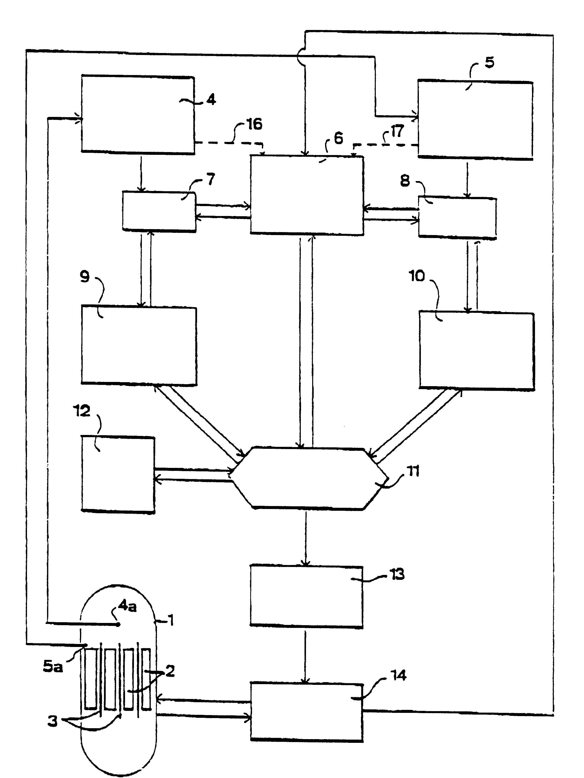
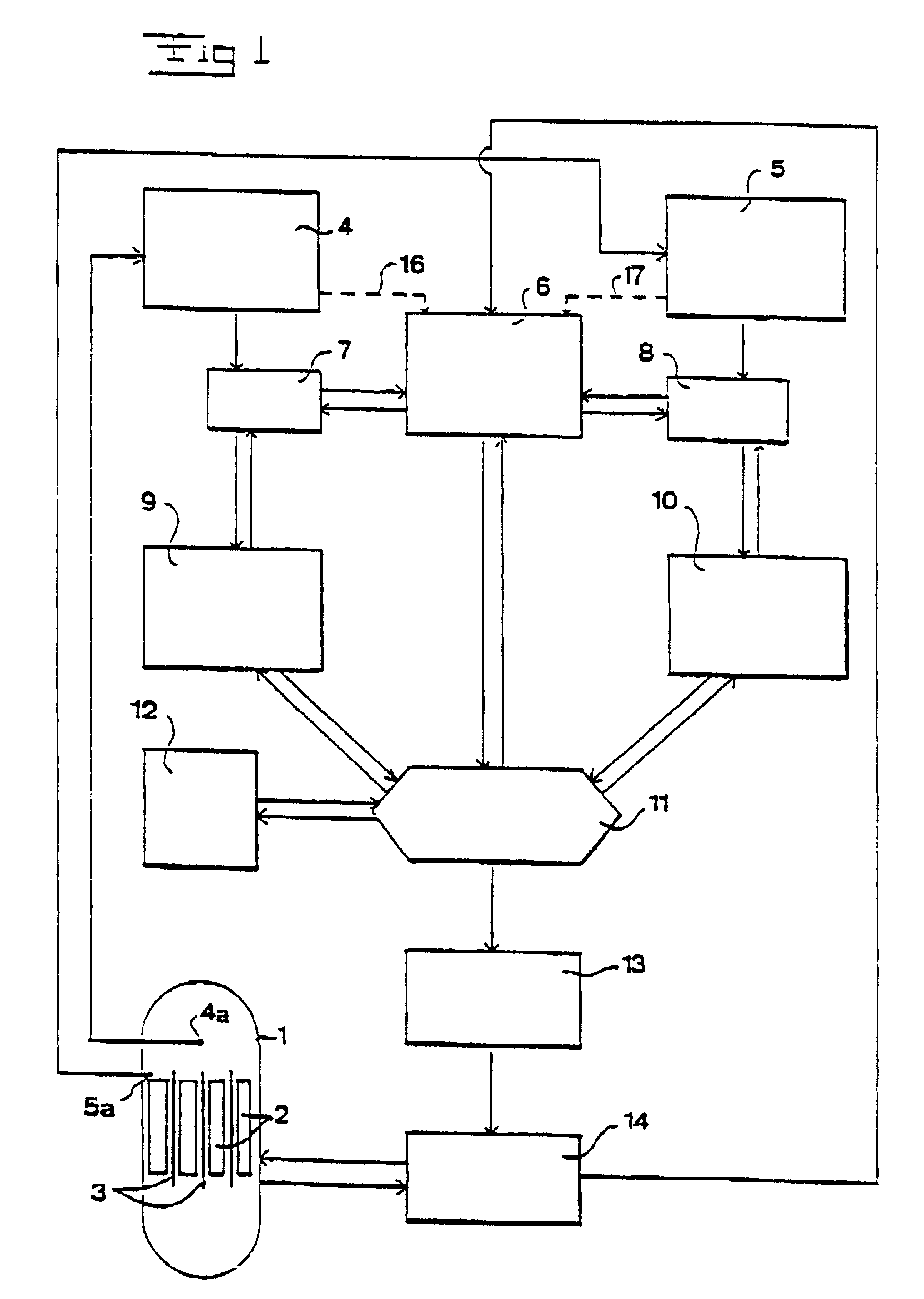
The method according to the invention is now to be described with reference to the flow chart of FIG. 1. The method is applicable to a nuclear plant having a reactor 1 which encloses a reactor core formed by a number of schematically disclosed fuel cladding members 2 which each encloses a number of nuclear fuel pellets. The reactor 1 is controlled by means of a number of control rods 3, which are displaceable into and out from the core between the fuel cladding members 2, and by regulating the water flow into and out from the core. It is to be noted that the flow chart disclosed in FIG. 1 is a model of a method for determining the integrity of the nuclear fuel. The invention is not limited to this model but the model may be designed in many different ways.

The box 4 represents a unit for determining the value of a number of parameters including activity data from the off-gases leaving the reactor 1. This unit 4 may for instance comprise a computer having a number of different detecto...


PUM


Abstract

The invention concerns a method and a device for evaluating the integrity of the nuclear fuel in a nuclear plant having a reactor (1) enclosing a reactor core formed by a number of fuel cladding members (2) arranged to enclose said nuclear fuel. The value of each of a number of parameters including activity data (4) of the off-gases from the reactor is determined. The value of each of a number of second parameters including chemical data and activity data of the liquid (5) flowing through the reactor is determined. The value of each of a number of operational parameters (6) including at least one of the reactor effects, control rod position, actual fuel type, flow of off-gases, and flow of the liquid flowing through the reactor is determined. The value of the first and second parameters are standardized (7, 8) in relation to the values of said operational parameters. The standardized values and the values of the operational parameters are analysed (9-11) and the integrity of the fuel is estimated based on the analysis. The invention also comprises producing guidelines for the continuing operation of the plant with regard to said estimation.

Description

THE BACKGROUND OF THE INVENTION AND PRIOR ARTThe present invention refers to a method and a device for evaluating the integrity of the nuclear fuel in a nuclear plant having a reactor enclosing a reactor core comprising a number of fuel cladding members in which said fuel is present.A core in a nuclear reactor comprises a plurality of fuel assemblies which are vertically provided with a certain distance from each other. The core is enclosed in a reactor vessel and submerged in a liquid, i.e. reactor water functioning as cooling medium as well as neutron moderator and flowing through the reactor vessel. The nuclear reactor also comprises a plurality of control rods which by being displaced into and out of the core regulate the effect produced by the reactor, and shut down and start, respectively, the reactor. A fuel assembly comprises a plurality of fuel rods vertically provided and each containing a staple of circular cylindrical, so called pellets of a nuclear fuel. Each fuel rod c...

Claims


Application Information

Patent Timeline
Patent Type & Authority Patents(United States)
IPC IPC(8): G21C17/04G21C17/00G21C17/02G21C17/06G21C17/07
CPCG21C17/00G21C17/04G21Y2002/204G21Y2004/401G21Y2002/207G21Y2002/304G21Y2002/502G21Y2002/205Y02E30/30
Inventor SIHVER, LEMBITARLEB.ANG.CK, INGERBJURMAN, BJORN
Owner WESTINGHOUSE ATOM
Why Eureka
Try Eureka