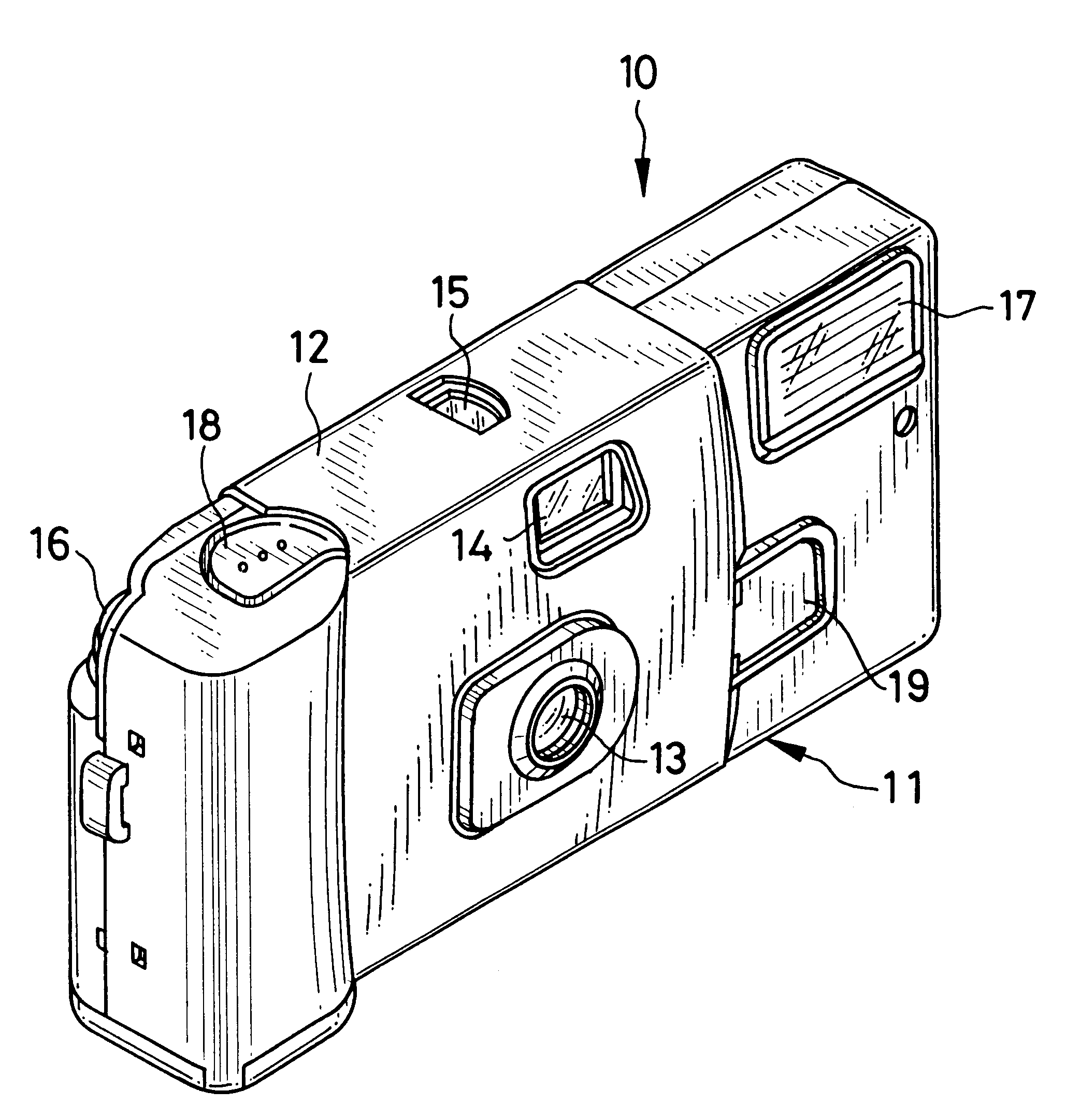
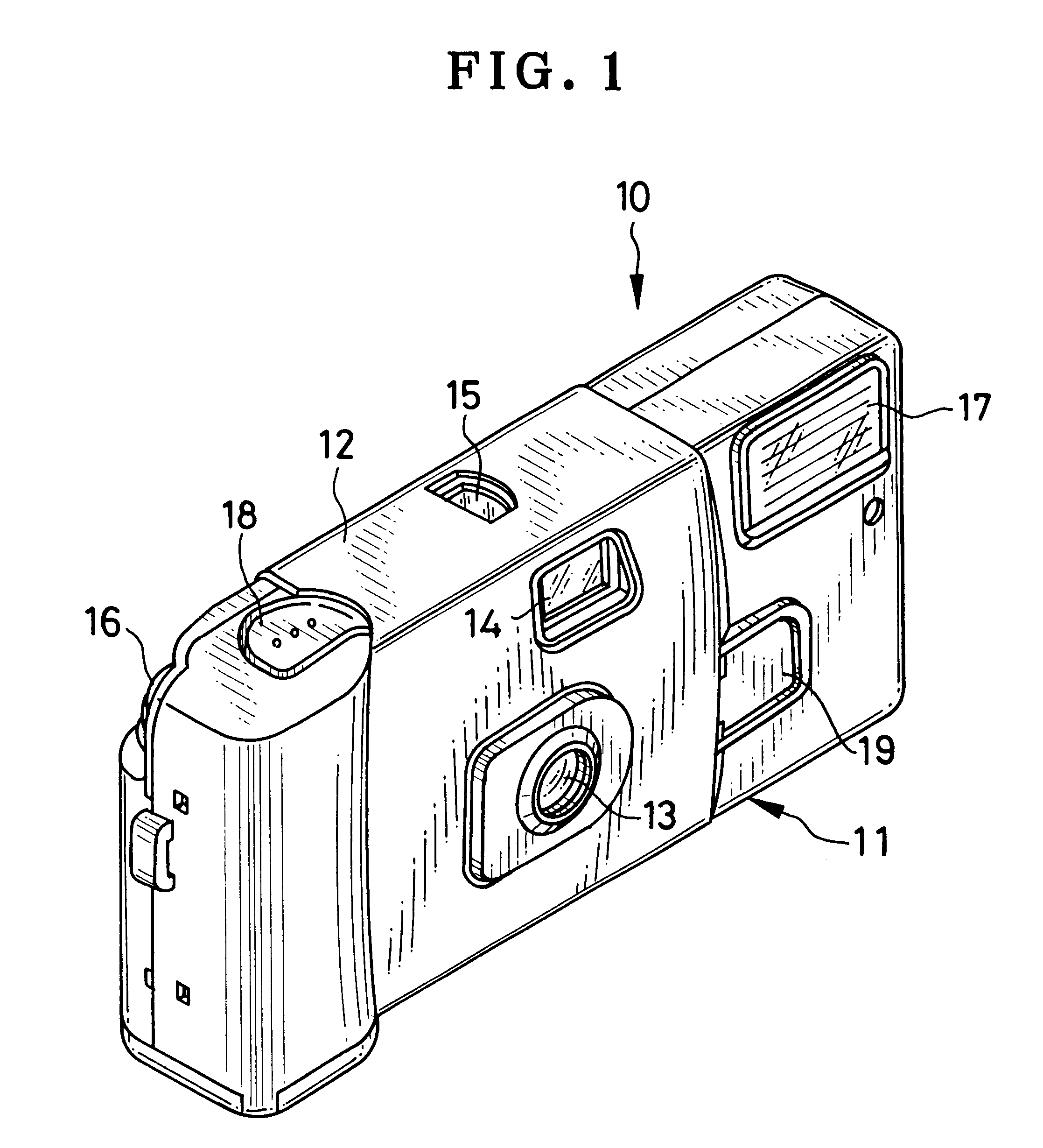
Flash unit

Inactive Publication Date: 2002-02-05
FUJIFILM CORP +1
View PDF10 Cites 7 Cited by
  • Summary
  • Abstract
  • Description
  • Claims
  • Application Information

AI Technical Summary

Problems solved by technology

As the Zener diode with high Zener voltage is expensive, it raises the cost of the flash circuit.
In addition, the conventional autostop flash circuit requires a lot of space for mounting various elements as above which are necessary for the automatic continuation and stopping of charging.
If the operation device is left in the charging position after the photography is terminated, the battery is wasted.
As a result, the battery runs down and it becomes

Method used


Image

  • Flash unit
  • Flash unit
  • Flash unit

Examples


Example

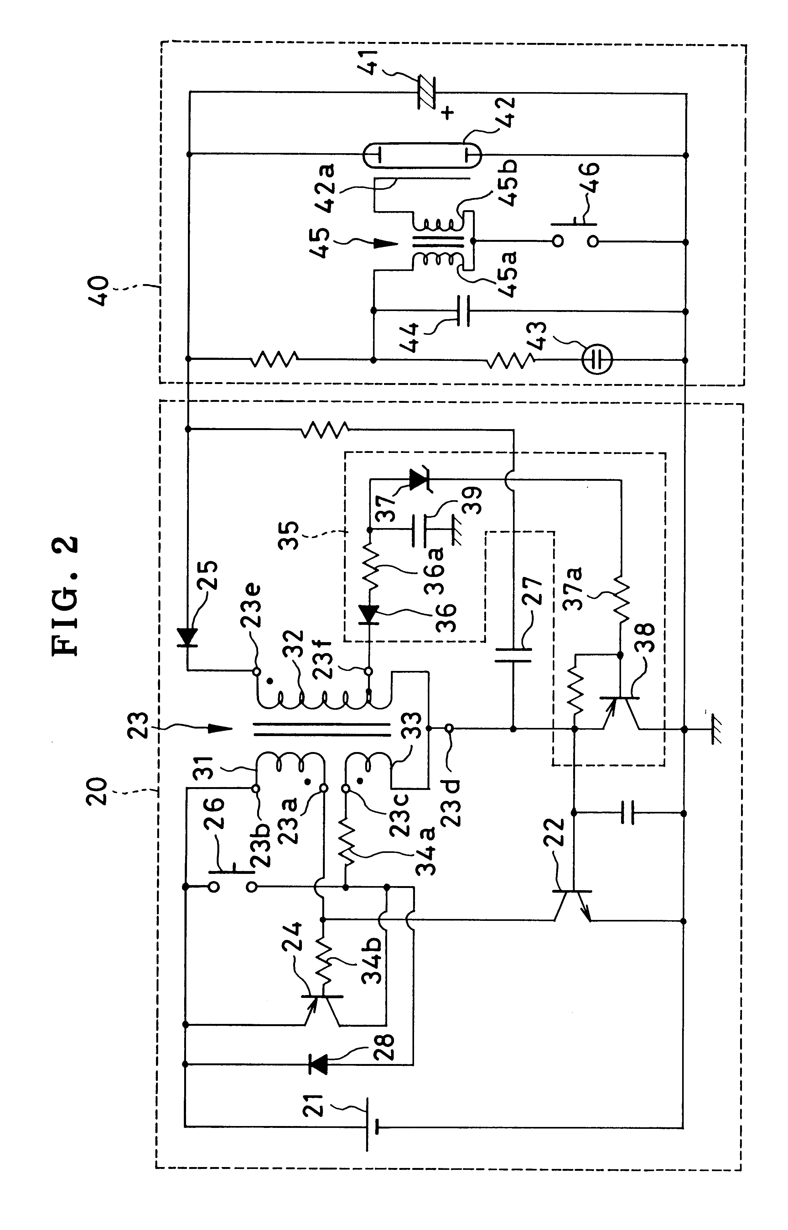
According to the second embodiment, an oscillation stopping circuit 35 is mainly constituted of a rectifying diode 36, a Zener diode 37 and a stopping transistor 38. The cathode of the rectifying diode 36 is connected to the tap point 23f, and the anode of the rectifying diode 36 is connected to the anode of the Zener diode 37 through a resistor 36a. The rectifying diode 36 is provided for rectifying the oscillating or alternating voltage at the tap point 23f, and tapping out only negative halves of the alternating voltage. The rectifying diode 36 also functions as a temperature compensating element for the Zener diode 37, as set force in detail later. A capacitor 39 is provided for smoothing the voltage from the rectifying diode 36, and applying it as a DC voltage to the Zener diode 37. The stopping transistor 38 has the base connected to the cathode of the Zener diode 37 through a resistor 37a, the emitter connected to the fourth terminal 23d of the oscillation transformer 23, and...


PUM


Abstract

In a flash circuit of a flash device, a Zener diode (37) is connected to a tap point (23f) located at an intermediate position of a secondary coil of an oscillation transformer (23). The oscillation transformer (23) and an oscillation transistor (22) constitutes an oscillation circuit. A potential at the tap point (23f) changes proportionally to a voltage charged in a main capacitor (41). When the main capacitor (41) is charged up to a set voltage, the Zener diode (37) conducts a Zener current, which activates a stopping transistor (38) and thus deactivates the oscillation circuit. When a flash charge switch (51) is turned on, an end of a light guide portion of a charge condition indicator (60) protrudes out of a lens-fitted film unit. When the main capacitor (41) is charged up to the set voltage, a light emission element starts lighting, and the light from the light emission element is projected from the end of the light guide portion.

Description

FIELD OF THE ARTThe present invention relates to a flash device, and more particularly to a flash device which is suitable for being incorporated in a lens-fitted photo film unit that contains a roll of photo filmstrip and is provided with a simple photographic mechanism including a taking lens.BACKGROUND ARTSWhen the subject brightness is so low that a proper exposure would not be provided without any artificial illumination, a flash device is often used to project light toward the subject synchronously with the shutter release. Since compact cameras and lens-fitted photo film units have an inexpensive lens system of a relative large f-number, most of them are provided with a built-in flash device. To make a flash photography, it is necessary to charge the main capacitor up to the set voltage prior to the shutter release. The conventional flash devices start charging in response to an actuation of a flash charge switch.A flash circuit has recently been known, for example from JPA 7...

Claims


Application Information

Patent Timeline
IPC IPC(8): G03B7/16G03B15/05H05B41/30H05B41/32
CPCG03B7/16H05B41/32G03B15/05G03B2215/0503
Inventor ISOZAKI, MAKOTOTAKAGI, JUNICHIKOIKE, KAZUMIMORIYA, MITSUHIROUCHIYAMA, KEIJIHATA, YUKITSUGU
Owner FUJIFILM CORP
Why Eureka
Try Eureka