Submarine power storage system

a power storage system and submerged technology, applied in the direction of caissons, drilling pipes, artificial islands, etc., can solve the problems of limited space, environmental disruption, limited size of the tank that can be built on land, etc., and achieve the effects of simple structure, high energy saving, and high energy saving

Inactive Publication Date: 2002-02-19
MITSUBISHI HEAVY IND LTD
View PDF26 Cites 28 Cited by
  • Summary
  • Abstract
  • Description
  • Claims
  • Application Information

AI Technical Summary

Benefits of technology

The tank thus manufactured on the sea can be easily installed on the seabed in a horizontal position. Namely, it suffices to pour water into the tank, while pulling the tank by tugboats, thus inclining the tank into a horizontal position, then to tow the tank to the installation site, further to pour water into the tank, thereby submerging the tank in the horizontal position, and finally to mount the tank on the tank base already secured to the seabed.
Hence, it can be expected that a large-scale submerged tunnel be built at low cost and within a short time, though the tunnel blocks are long and huge ones. Moreover, the construction of the tunnel can be started at any point in the planned route or at two or at more points at the same time, because the tunnel blocks can be manufactured simultaneously on the sea. This helps shorten the time required for building the submerged tunnel.

Problems solved by technology

Hence, tanks that can be built on land are limited in size.
More specifically, if a large tank is manufactured on the land, its size is limited by the size and proof strength of the dock, and also by the draft of the dock and the depth of the neighboring water passages.
The carbon dioxide gas (carbon oxide gas) generated in the thermal power plant will result in environmental disruption such as air pollution.
With the method (1) it is difficult to dissolve the carbon dioxide gas sufficiently.
Furthermore, there exists the danger that the carbon dioxide gas blows up over the sea surface.
This is because the liquefied or solidified carbon dioxide is dissolved in the sea water, inevitably increasing the carbon dioxide concentration in the sea water, making the sea water strongly acid.
The methods (2) and (3) may also induce environmental changes because it lowers the temperature of sea water.
Further, a great amount of energy is required to perform the methods (2) and (3), in which carbon dioxide is solidified into dry ice and liquefied, respectively.
The conventional power system is disadvantageous in the following respect.
However, geographical conditions for a pumped storage power system are restrictive, and the building cost of the system is increasing much.
In view of this, it has become difficult to construct new pumped storage power plants.
This is because earthquakes may happen at the seabed on which the system is installed.
In fact, it would be extremely difficult to satisfy such a demand as described above.
With this plant it is difficult to store more electric power.
At present there is no land large enough to build so many tanks.
From an economical point of view, too, it is difficult to build these tanks.
It would be dangerous, as is pointed out, that LNG tankers frequently navigate along a gulf coast where thermal power plants are densely constructed, because the LNG tankers may likely to collide with each other.
The use of either material complicates the structure of the LNG tanks.
This renders it difficult, from an economical viewpoint, to build LNG tanks of this type.
This inevitably makes the tanks complex in structure.
This maintenance of temperature is a hindrance.
Once a trouble has developed in the pump immersed in LNG, the plant cannot help but be stopped.
Geographical, economical, cooling and LNG-supplying conditions for an LNG storage system can hardly be satisfied.
As a matter of fact, it has hitherto been considered to be difficult to reserve (store) LNG for so long a time as petroleum.
Besides, it usually takes a long period of time to dig the tunnel in the seabed.
Further, the technique can build a tunnel within a short period of time.
It is difficult, however, to manufacture such gigantic tunnel blocks on the ground, for some reasons.
Furthermore, manufacturing tunnel blocks on the ground requires much cost and many man-hours.
A considerably high cost and a number of man-hours are required only to deposit concrete.
Due to these facts, it is regarded as impossible to manufacture big and long tunnel blocks on the ground.
Further it is considered difficult to shorten the time of building a submerged tunnel.
These hinder the construction of a large-scale submerged tunnel.

Method used


Image

  • Submarine power storage system
  • Submarine power storage system
  • Submarine power storage system

Examples


embodiment 1

A method of building a large tank, which is an embodiment of the invention, will be described with reference to FIGS. 1 to 13.

This embodiment is a method of building a large cylindrical tank on the seabed, in a horizontal position.

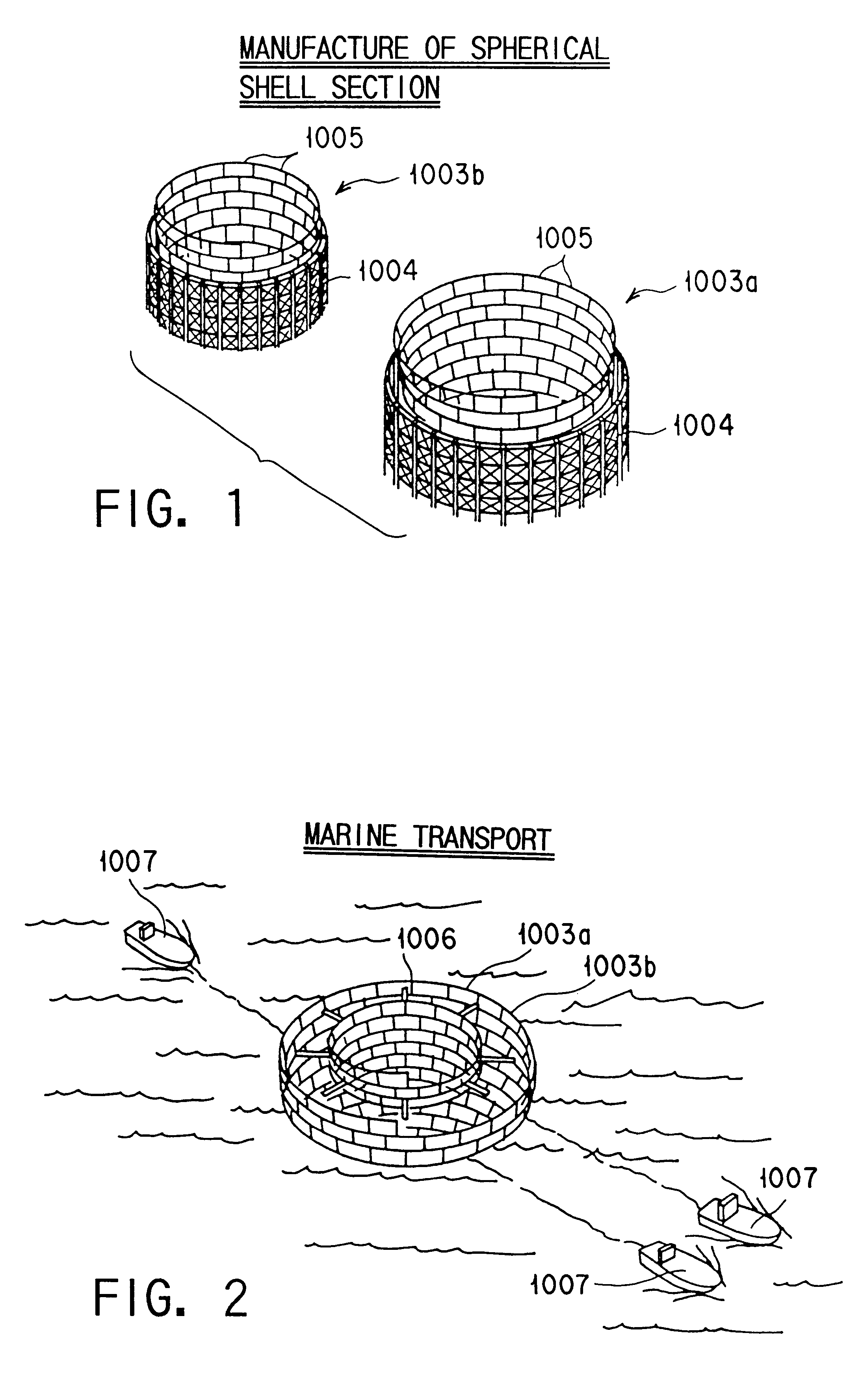
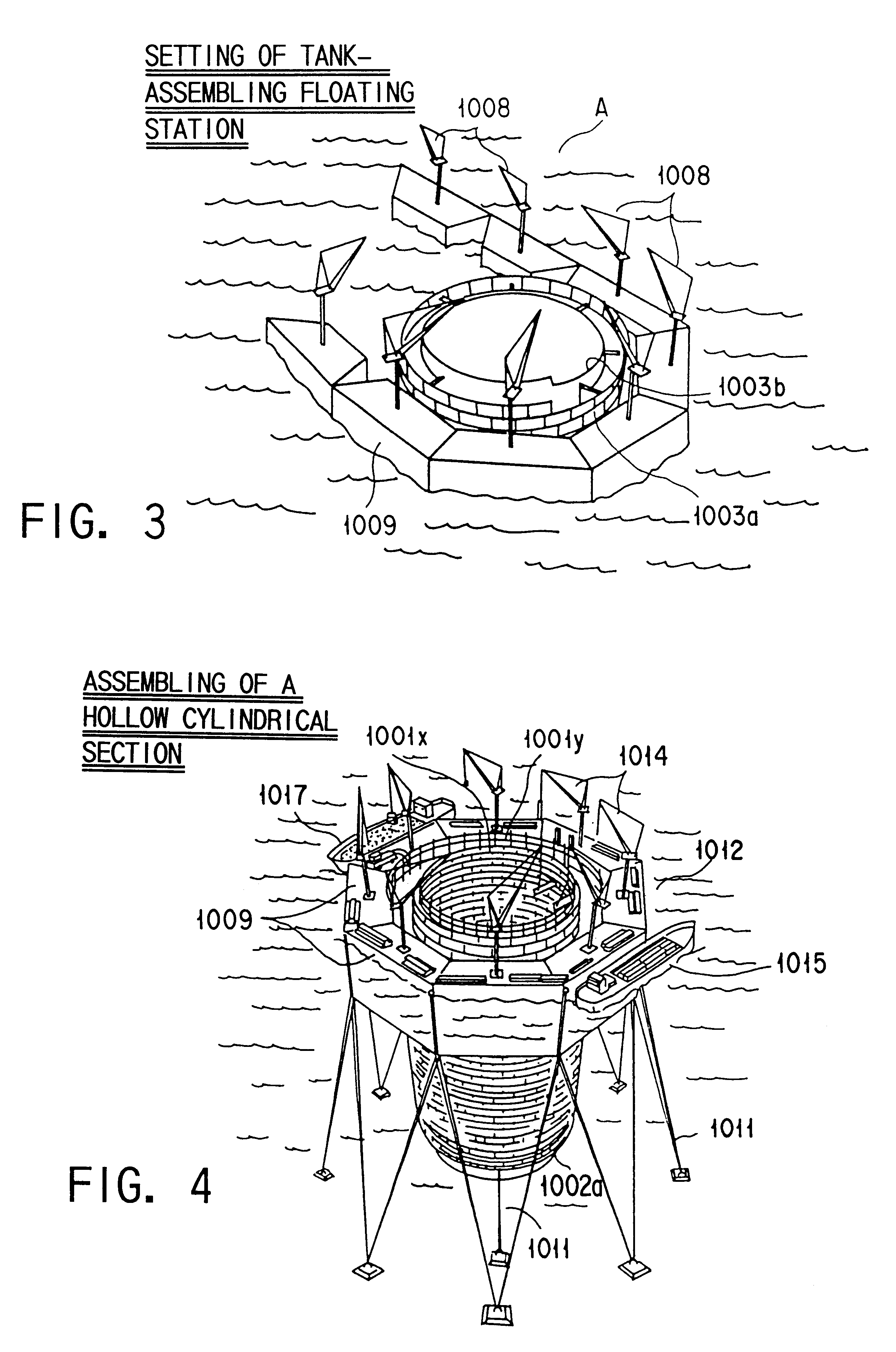
As shown in FIGS. 12 and 13, the large tank 1001a is a horizontal cylindrical tank. It comprises a cylindrical section 1001 and spherical shell sections 1002a and 1002b connected to the ends of the cylindrical section 1001. The cylindrical section 1001 is a cylindrical double wall made of, for example, steel plates 1014. The space in the double wall is filled with concrete. Each of the spherical shell sections 1002a and 1002b is made of a double wall composed of, for example, steel plates. The space in the double wall constituting either spherical shell section is filled with concrete.

To build the large tank 1001a, both spherical shell sections 1002a and 1002b are assembled on the land, for example in a factory as is illustrated in FIG. 1. More correctly, ...

embodiment 2

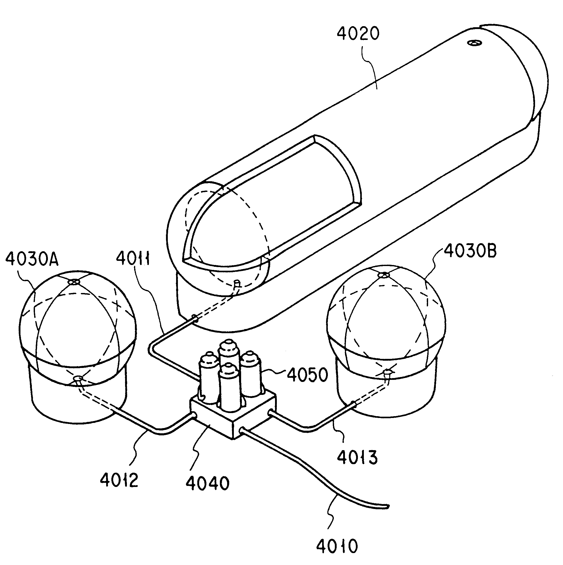
A combined system for deep-sea power storage and carbon dioxide dissolution, according to the second embodiment of the invention, will be described.

FIG. 14 shows the combined system for deep-sea power storage and carbon dioxide dissolution. FIG. 15 is a plan view illustrating a tank and electrical / mechanical component units incorporated in the system shown in FIG. 14. FIG. 16 is a sectional view taken along line III--III shown in FIG. 15. FIG. 17 is a sectional view taken along line IV--IV shown in FIG. 15.

As shown in FIG. 15, the combined system comprises a tank 2001 and a plurality of electrical / mechanical component units 2002, a transformer section 2004, and a carbon dioxide source 2006. For example, two electronic component units 2002 are provided adjacent to the tank 2001. The transformer section 2004 is installed on the ground and connected to the units 2002 by a submarine cable 2003, for controlling the power storage and power generation performed in each unit 2002. The carbo...

embodiment 3

FIG. 18 is a diagram illustrating a deep-sea power storage system according to the present invention. As shown in FIG. 18, the system comprises a system body 3001 installed on the seabed 3002.

The system body 3001 is connected by a submarine cable 3004 to a ground facility 3003 installed on the ground. An operator stationing in the ground facility 3003 remotely controls the system body 3001, thereby accomplishing maintenance work including routine inspection and routine oiling, causing the system body 3001 to dive and float, and switching the operating mode between the power-generating mode and the power-storing mode.

In the figure, numeral 3005 designates a support diving vehicle, in which the personnel perform maintenance on the system body 3001 immediately after the body 3001 has been installed.

FIG. 19 shows the system body 3001. The system body 3001 has a battery tanks 3011 and electrical / mechanical component containers 3012 (two tanks as shown in FIG. 19). The battery tank 3011 a...


PUM


Abstract

A submarine power storage system includes a unit base constructed on the floor of the sea, which base has seats for a plurality of electromechanical containers. Each such container has a turbine, a generator, a motor and a pump. The system also includes a plurality of battery tanks which are connected to the unit base.

Description

The present invention relates to a method of manufacturing a large tank for use as an oil tank or a CO.sub.2 storage tank, for use in building a submerged tunnel, a submarine living quarter or a submarine station, or for use as a battery tank.The invention also relates to a combined system for deep-sea power storage and carbon dioxide dissolution.Further, the invention relates to a deep-sea power storage system for generating electric power by using sea water.Still further, the present invention relates to a submarine power storage system which is installed in the deep sea and which stores electric power by utilizing the pressure of sea water.Moreover, this invention relates to a submarine storage system designed to store, for example, LNG.Furthermore, the present invention relates to a method of building a submerged tunnel for drive ways and railroads, which runs on the seabed.Conventionally, a submarine tank is built on land, in a horizontal position in a dock large enough to hold...

Claims


Application Information

Patent Timeline
Patent Type & Authority Patents(United States)
IPC IPC(8): E02D15/00E02D29/063E02D29/07E02D29/073E02D29/09E02D29/00E02B17/00E02D15/06E04H7/00
CPCE02B17/00E02D15/00E02D15/06E04H7/00E02D29/063E02D29/07E02D29/073E02D29/06E02B2017/0039
Inventor MORISHIGE, HARUO
Owner MITSUBISHI HEAVY IND LTD
Why Eureka
Try Eureka