Liquid ejecting method and liquid ejecting head

a liquid ejecting head and liquid ejecting technology, applied in printing and other directions, can solve the problems of excessive bubble growth, increase the number of liquid droplets to be ejected, and reduce the recording speed, and achieve the effect of high speed

Inactive Publication Date: 2002-02-26
CANON KK
View PDF33 Cites 39 Cited by
  • Summary
  • Abstract
  • Description
  • Claims
  • Application Information

AI Technical Summary

Benefits of technology

is to provide a reliable liquid ejection method, that is, a liquid ejecting method which does not suddenly fail to eject liquid, i.e., a liquid ejecting method which makes high speed recording possible with the use of a bubble jet type liquid ejecting head, in particular, so-called side shooter type liquid ejecting head in which ejection orifices for ejecting extremely small liquid droplets at a high frequency are disposed at a high density, directly facing heat generating members one for one, and in which a bubble is allowed to become connected to the atmosphere.

Problems solved by technology

Recording an image with the use of finer liquid droplets increases the number of liquid droplets to be ejected, which in turn reduces recording speed.
If the pulse duration is greater than 3.5 .mu.sec., bubble growth becomes excessive, which makes the location of the meniscus after the liquid ejection excessively far from the ejection orifice.
As a result, refilling time becomes longer, which makes the liquid ejecting head unsuitable for high speed recording.
If the duration of the pre-pulse exceeds 1.5 .mu.sec, and / or the interval between the pre-pulse and the main pulse exceeds 2.0 .mu.m, bubble growth becomes excessive, which in turn causes the meniscus to retract by a greater distance.
If the driving voltage is no more than 1.1 times the threshold voltage Vth, liquid ejection velocity is excessively low, causing liquid droplets to be ejected off the predetermined course, provided that bubbles are generated and liquid droplets are ejected.
On the contrary, if the driving voltage value is no less than 1.3 times the threshold voltage Vth, bubble length becomes excessive, causing the meniscus to retract by a greater distance, which in turn prolongs refilling time, and / or excessively increases liquid ejection velocity, increasing the amount of the splash which occurs as a liquid droplet hits the recording medium.
Further, there is no force which works to pull the instable liquid back into the liquid path, and therefore, the instable liquid adjacent to the ejection orifice 4 cannot be prevented from splashing.
Further, since the size of the imaginary bottom surface of the ejection orifice is greater than the imaginary top surface of the ejection orifice, it is more difficult for the recording liquid to plug the ejection orifice.
On the contrary, if the minimum distance across the horizontal section of the ejection orifice through the center of the section is no more than the twice the orifice plate thickness (if the distance between the imaginary top and bottom surfaces of the ejection orifice is no less than half the minimum distance across the horizontal section of the ejection orifice through the center of the section), the ratio at which the aforementioned phenomenon occurs is extremely high, that is, high enough to create problems in terms of practical usage.
If 6 .mu.m.gtoreq.Tn, that is, if the height of the liquid path is excessively reduced, the viscous resistance of the liquid path excessively increases, prolonging refilling time, and therefore, the liquid ejecting head cannot be driven at high frequency.
If the velocity at which liquid droplets are ejected is less than 10 m / sec, liquid droplets are likely to miss the intended spots on the recording medium, which is possible to reduce print quality.
As a result, ink droplets missed intended spots on the recording medium.
Therefore, refilling time is long, and long refilling time makes it impossible for the head to be driven at a high frequency, which is a problem.
The meniscus vibration thereafter was at an undetectable level, and had virtually no effect upon printing quality.

Method used


Image

  • Liquid ejecting method and liquid ejecting head
  • Liquid ejecting method and liquid ejecting head
  • Liquid ejecting method and liquid ejecting head

Examples


embodiments 3-5

In Embodiments 3-5, the same ink as the one employed in Embodiments 1 and 2 was employed.

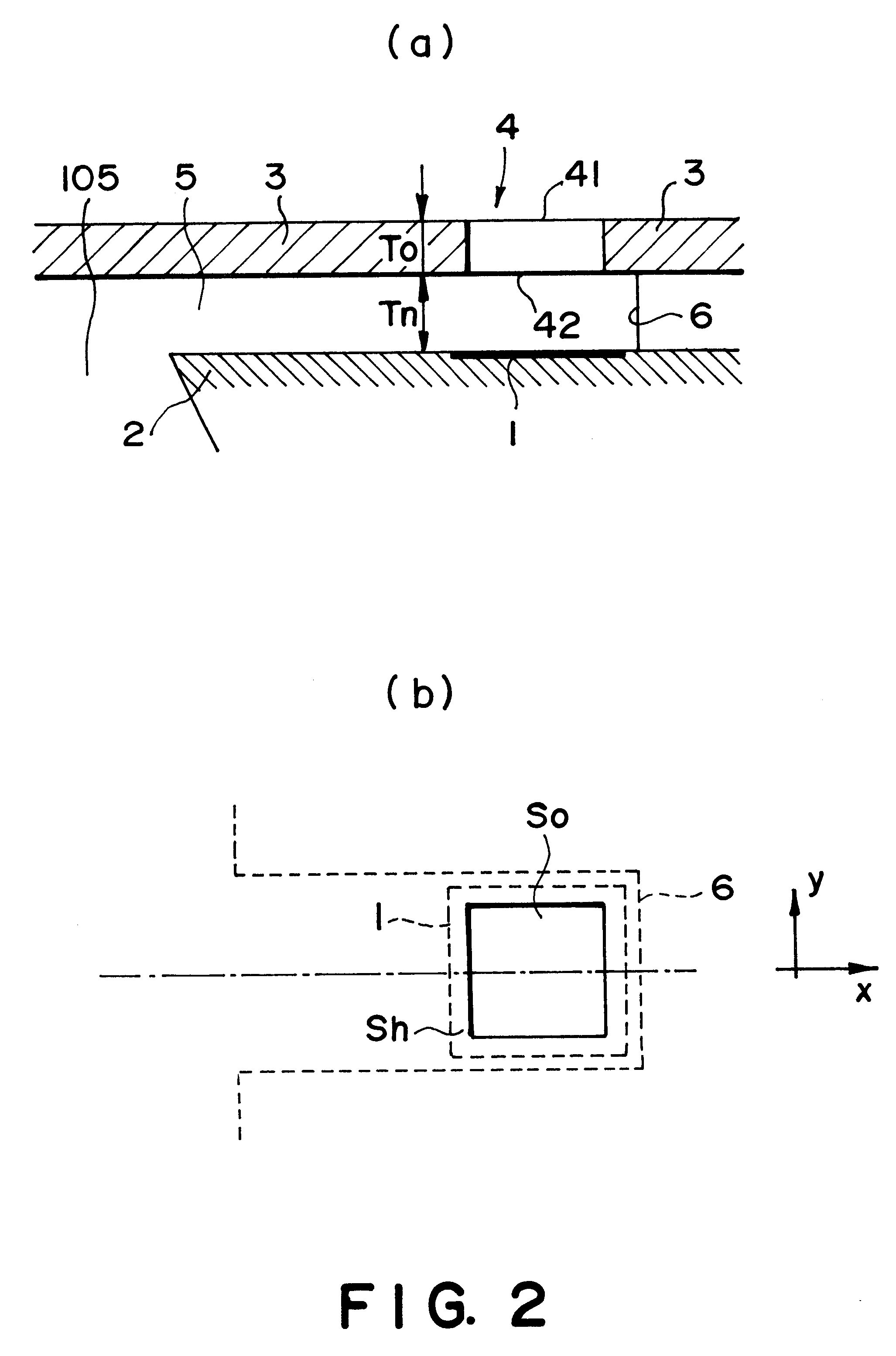
As for the height Tn of each liquid path, it was made to be 12 .mu.m in Embodiments 3 and 4, and 6 .mu.m in Embodiment 5 . As for the thickness To of the orifice plate, it was made to be 7 .mu.m in Embodiment 3, and 6 .mu.m in Embodiment 4. In Embodiment 5, it was made to be 9 .mu.m.

In Comparative Examples 5-10, the size So of each ejection orifice was made to be 220 .mu.m.sup.2, 314 .mu.m.sup.2, 227 .mu.m.sup.2, 202 .mu.m.sup.2 (14.2 .mu.m square), 324 .mu.m.sup.2, and 324 .mu.m.sup.2, correspondingly. The size Sh of the heating surface of each heater was made to be the same as that for Embodiments 3-5, which was 570 .mu.m.sup.2 (24 .mu.m.times.24 .mu.m). The height Tn of each liquid path in Comparative Examples 5-10 was made to be 12 .mu.m, 4 .mu.m, 8 .mu.m, 12 .mu.m, 6 .mu.m and 5.0 .mu.m, correspondingly, and the thickness To of each orifice plate was made to be 9 .mu.m, 11 .mu.m, 9 .mu.m, 9...

embodiment 4

In Embodiment 4 and Comparative Example 8, the opening of each ejection orifice was square, which was different from the shapes of the openings in other embodiments and comparative examples, in which they were in the form of a true circle. Even in Comparative Example 6 in which the shape of the opening of the ejection orifice was truly circular, the sudden ejection failure occurred just as in the other heads, the openings of the ejection orifices of which were truly circular. In Embodiment 4, D / To was 2.5, which was desirable since it was greater than 2. Even though the opening of the ejection orifice was square, the sudden ejection failure did not occur. In consideration of the deformation caused by the pressure generated by bubbles, the thickness To of the orifice plate is desired to be no less than 4 .mu.m.

Further, in order to accurately evaluate the aforementioned embodiments and comparative examples in terms of color density and sudden ejection failure, the liquid ejecting head...


PUM


Abstract

A liquid ejecting method using a liquid ejecting head having electrothermal transducer elements for generating thermal energy sufficient to create bubbles in liquid and ejection outlets disposed opposed to the electrothermal transducer elements which are arranged at a density not less than 300 per 25.4 mm in a line, the liquid ejection head also having liquid flow paths in fluid communication with the ejection outlets, respectively, wherein the bubble generated by the thermal energy generated by the electrothermal transducer element is brought into communication with ambience while an internal pressure of the bubble is less than an ambient pressure, and wherein droplets having volumes not more than 15x10-15 m3 are ejected at a frequency not less than 7 kHz, said method includes the improvement wherein the liquid flow path of the liquid ejecting head has a height not less than 6 mum, and a distance between an upper surface and a lower surface of the ejection outlet is not more than one half of a minimum opening distance through a center of the ejection outlet.

Description

FIELD OF THE INVENTION AND RELATED ARTThe present invention relates to a liquid ejecting method and a liquid ejecting head which are used for ejecting droplets of liquid such as ink toward various recording media, such as paper, for the purpose of recording. In particular, it relates to a liquid ejecting method for ejecting extremely small droplets of liquid at an extremely high frequency, and also, a liquid ejecting head, that is, a recording head, which comprises a plurality of liquid paths arranged at a high density to realize high resolution.Among various liquid ejecting methods are so-called bubble jet type liquid ejecting methods. According to these methods, bubbles are rapidly grown in liquid, and the pressure generated by the bubble grown is used to eject droplets of liquid from liquid ejection orifices. These methods are high in liquid ejection response, and therefore, are excellent for high speed recording and high density recording.Among the bubble jet type liquid ejectin...

Claims


Application Information

Patent Timeline
Patent Type & Authority Patents(United States)
IPC IPC(8): B41J2/14
CPCB41J2/14024B41J2/1404B41J2002/14387B41J2002/14169
Inventor TACHIHARA, MASAYOSHITAMURA, YASUYUKIMURAKAMI, SHUICHI
Owner CANON KK
Why Eureka
Try Eureka