Cable deployment system and method of using same

a deployment system and cable technology, applied in the field of cable deployment systems, can solve the problems of affecting the cost effectiveness of high-reliability installation, affecting the reliability of installation, and the laying of cable laying vessels that are not well suited to handling short cable lengths,

Inactive Publication Date: 2002-02-26
SAIPEM AMERICA
View PDF20 Cites 72 Cited by
  • Summary
  • Abstract
  • Description
  • Claims
  • Application Information

AI Technical Summary

Problems solved by technology

All cables known to have been laid on the sea floor in deep water are long lines and/or are suitable for fabrication with a strength member, or have in some way compromised the need for cost effective, highly reliable installation.
Conventional cable laying vessels are not well suited for handling short cable lengths.
Furthermore, since laying short cables does not economically justify employment of a purpose built cable lay vessel, there is a need for a cable laying technique that is compatible with vessels of opportunity.
Seismic cable cannot be subjected to tensile forces or compressive loads, which would damages the geophones or break the fine electrical conductors in the cable.
Laying seismic cable by hanging it from the deck of a vessel to the sea floor would result in high load forces in the cable due to the weight of suspended cable, vessel heave, water currents, and other perturbations.
Lashing the cable to a strength member, such as a wire rope, is a hazardous activity for deck crews, and it extends the vessel time requir

Method used


Image

  • Cable deployment system and method of using same
  • Cable deployment system and method of using same
  • Cable deployment system and method of using same

Examples


Embodiment Construction

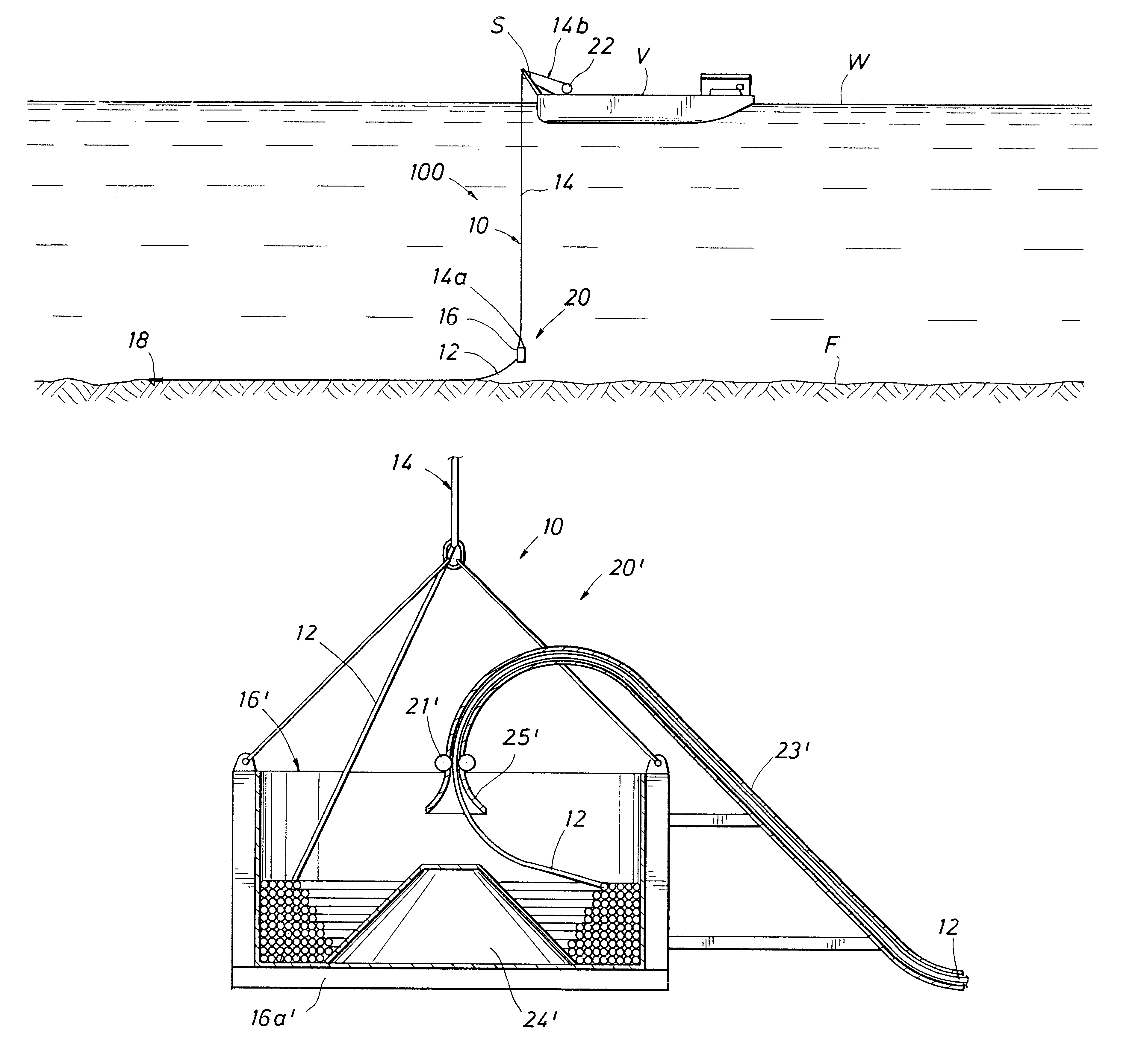
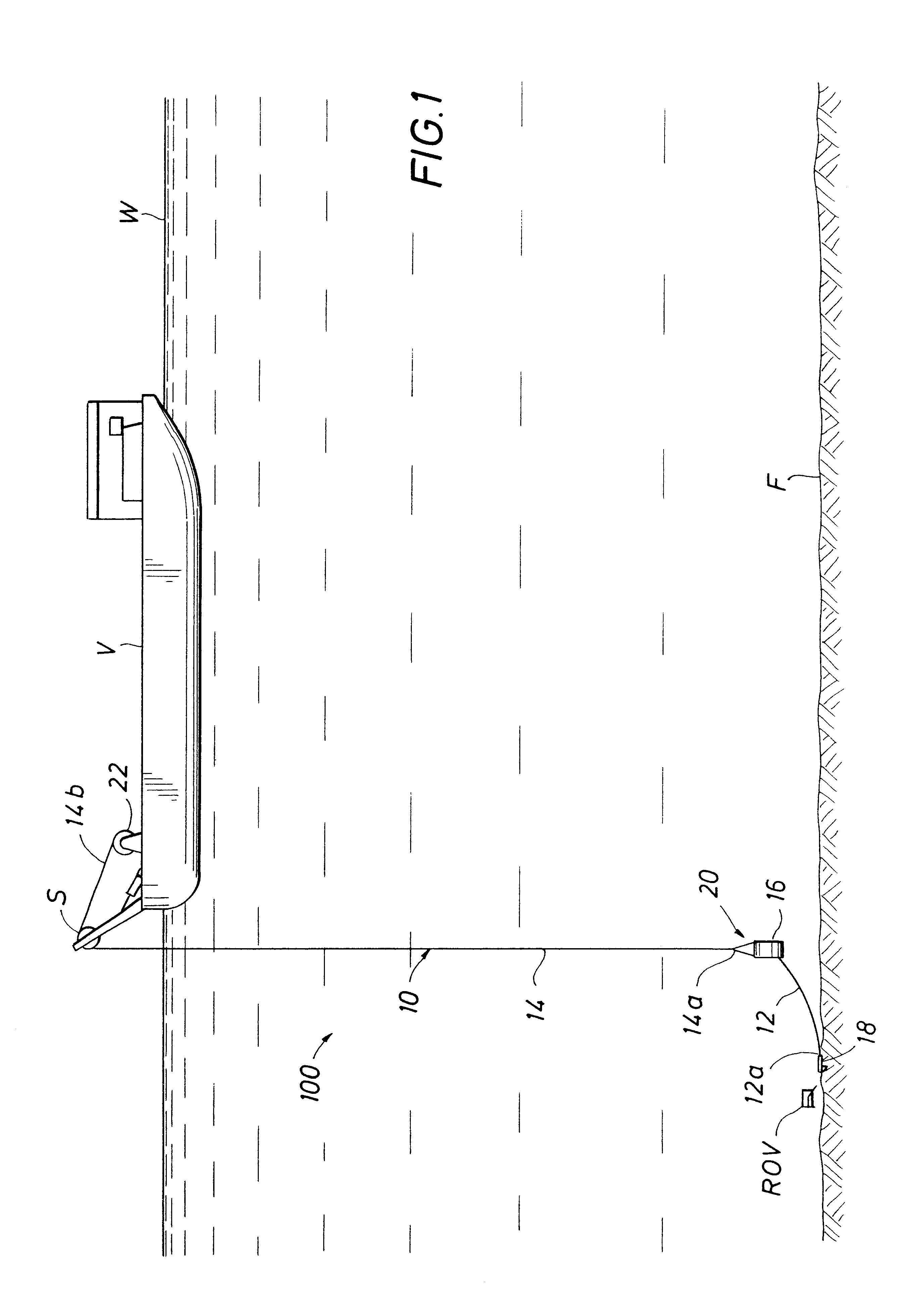
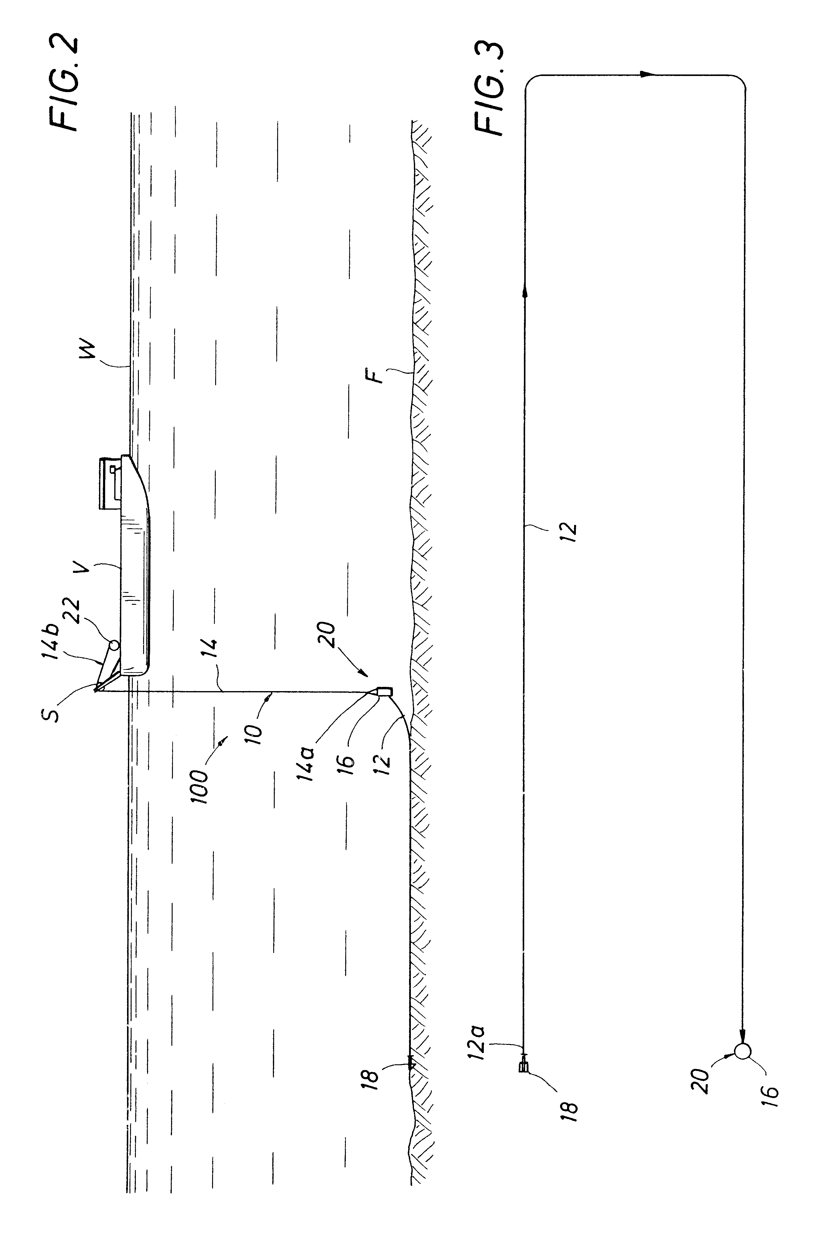
The cable deployment system 100 of the present invention will now be described in detail with reference to the drawings. Referring to FIG. 1, a cable, generally referred to as 10, includes a first cable section 12 and a riser cable section 14. Referring to FIGS. 1, 5, 6, 9 and 10, the first cable section 12 is coiled inside a drum 16, preferably cylindrical, of sufficient size to accommodate the allowable bend radius of the first cable section 12 and to hold the required length of the first cable section 12. As will be described below, the first cable section 12 has a length sufficient to form the desired cable layout on the sea floor F. The cylindrical drum 16, when fitted with the described equipment and instrumentation constitutes the submersible cable deployment system 20. The submersible cable deployment system 20 provides an integrated transportation and deployment system as will be explained below. It is to be understood that one embodiment of the submersible cable deployment...


PUM


Abstract

A cable deployment system and method for laying a cable on the sea floor. The cable deployment system includes a cable having a first cable section connected to a riser cable section. The riser cable section includes an armor that is connected to a drum capable of containing a required length of the first cable section. A stinger is attached to the drum and shaped to allow the first cable section to exit the drum. The cable deployment system also includes a tensioning device attached to the drum. The tensioning device is capable of maintaining a tension in the first cable section during deployment of the first cable section from the drum. The method of deploying the cable in deep water from a surface vessel includes the steps of containing the first cable section within the drum and lowering the drum from the surface vessel. An end of the first cable section is secured to the sea floor and the first cable section is deployed from the drum onto the sea floor.

Description

1. Field of the InventionThe present invention relates generally to cable deployment systems for laying cables on the sea floor in deep water and a method of using the cable deployment system for laying cables on the sea floor.2. Description of the Related ArtOffshore oil production has only moved into the very deep waters in recent years, and all known seismic surveys to date in deep water have been done with seismic cables towed behind a vessel of opportunity. New seismic techniques are presenting the need to lay relatively short cables having a total length of only 3 to 5 times the water depth. These new seismic techniques require permanently installing seismic arrays on the sea floor to monitor the depletion of deep water hydrocarbon reservoirs.The prior art of laying cables on the sea floor in deep water has concentrated primarily on long lines such as intercontinental telecommunications lines. All cables known to have been laid on the sea floor in deep water are long lines and...

Claims


Application Information

Patent Timeline
IPC IPC(8): G02B6/50G02B6/46H02G1/10
CPCH02G1/10G02B6/506
Inventor BATH, WILLIAM R.HOLTZ, GARY L.SAYLE, FRANKYEMINGTON, CHARLES R.
Owner SAIPEM AMERICA
Why Eureka
Try Eureka