
EL display device and driving method thereof

a technology of el display device and display device, which is applied in the direction of static indicating device, electroluminescent light source, instruments, etc., can solve the problems of display device, low red itself of an image displayed on the el display device, unsatisfactory white balance, etc., and achieves unsatisfactory white balance. , the effect of unsatisfactory white balan

Inactive Publication Date: 2002-02-26
SEMICON ENERGY LAB CO LTD
View PDF4 Cites 61 Cited by
  • Summary
  • Abstract
  • Description
  • Claims
  • Application Information

AI Technical Summary

Benefits of technology

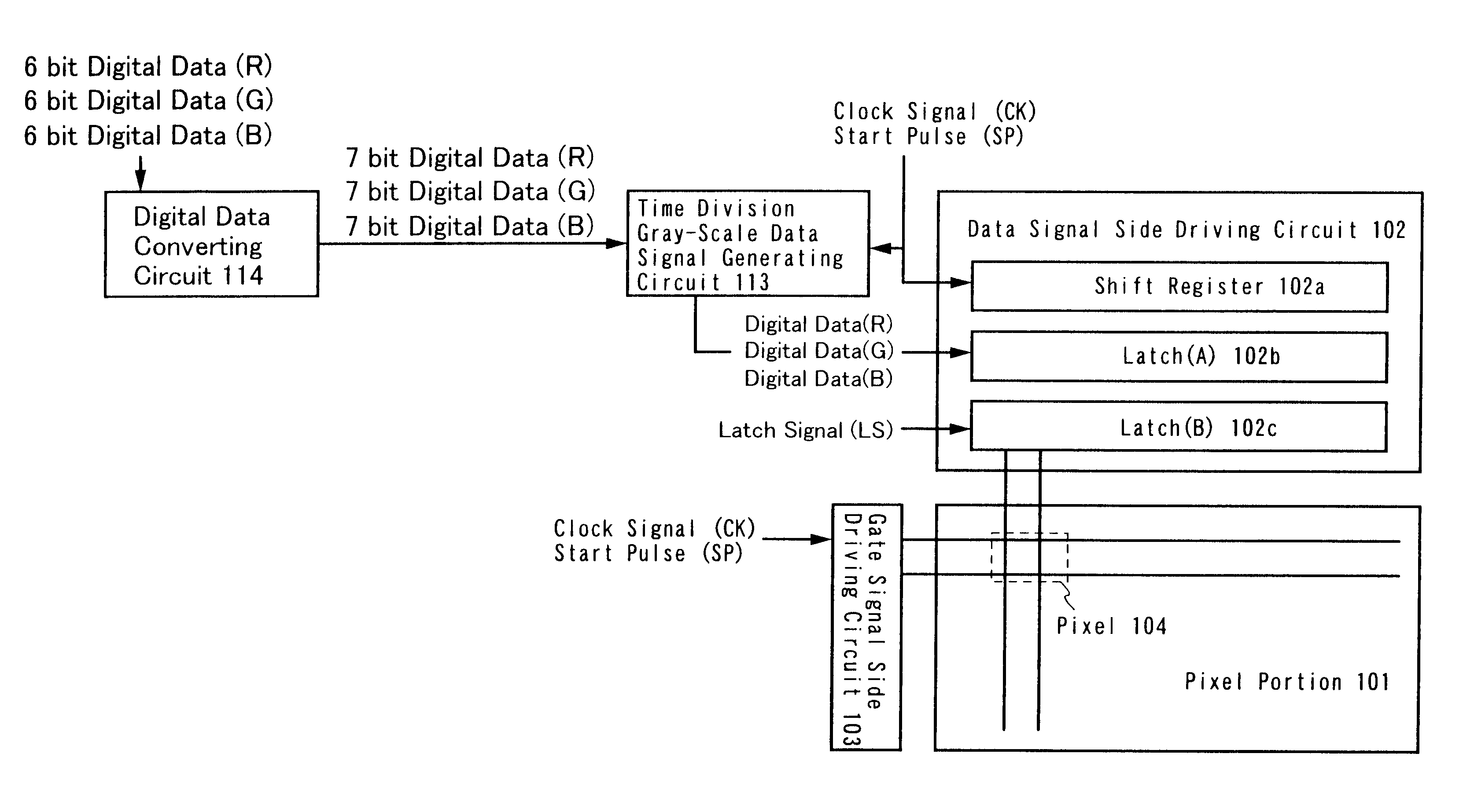
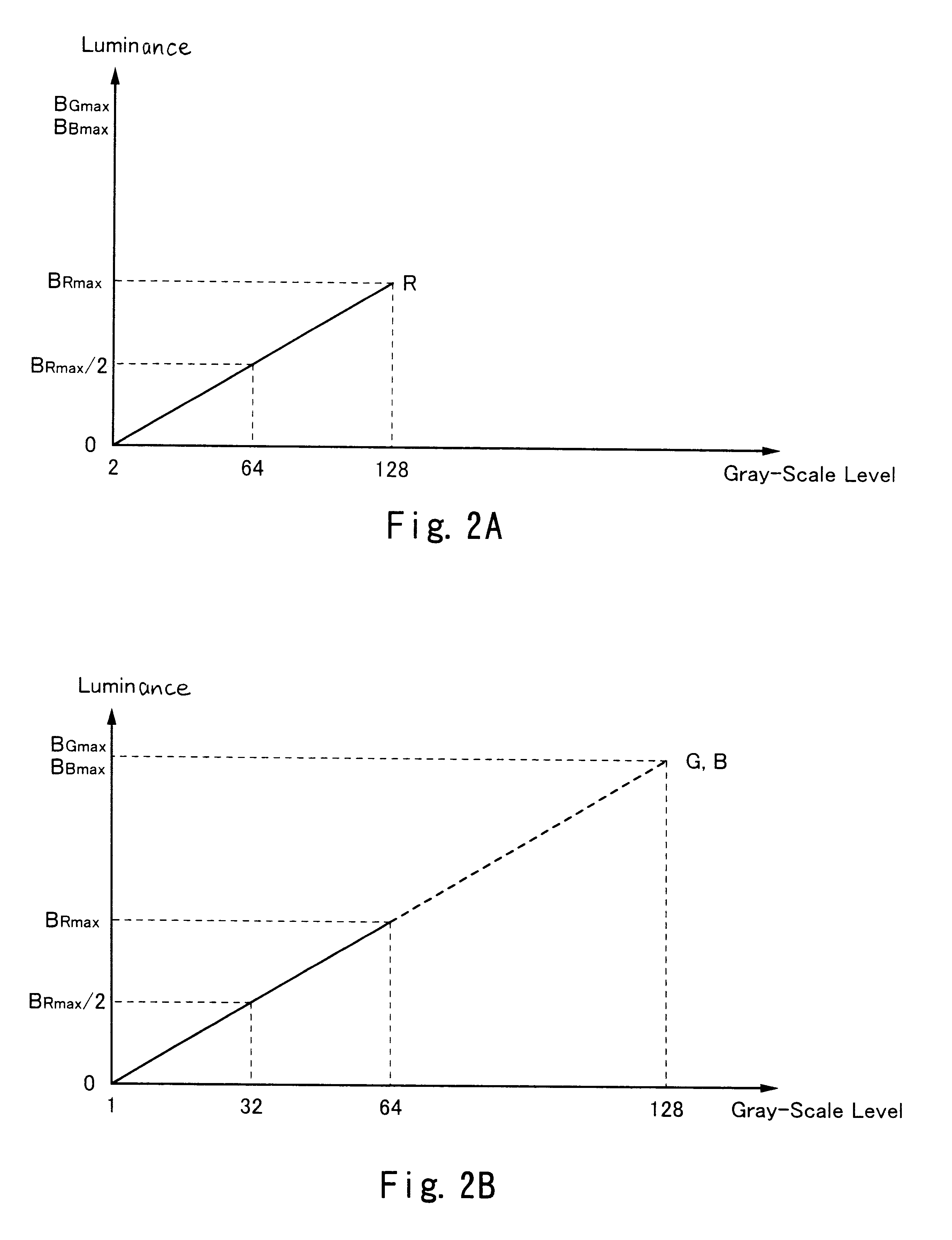
A method of driving an EL display device according to the present invention is now described. In the driving method according to the present invention, in view of the lower luminance of red light emission of the EL light emitting layer, by suppressing the luminance of a green image and the luminance of a blue image, the luminance of a red image, the luminance of a green image, and the luminance of a blue image are well-balanced, which makes it possible to improve the white balance. It is to be noted that the present invention can be applied not only to EL light emitting elements using an EL light emitting layer which emits white light and a color filter but also to EL light emitting elements using an EL light emitting layer which emits red light, an EL light emitting layer which emits green light, and an EL light emitting layer which emits blue light.

Problems solved by technology

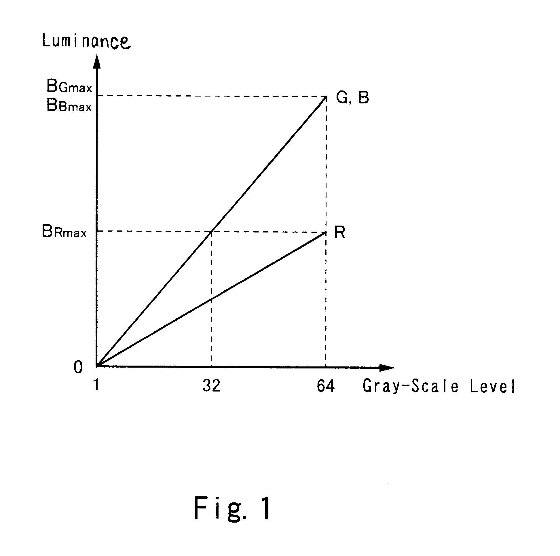
However, in this case also, the luminance of red itself of an image displayed on the EL display device is low, and an image which is intended to be displayed in red is displayed in orange.
As a result, only a display device, which has unbalanced luminance of red, green, and blue light emission and unsatisfactory white balance, can be provided.
However, since the maximum value B.sub.Rmax of the luminance of red light emission is half of the maximum value B.sub.Gmax of the luminance of green light emission or half of the maximum value B.sub.Bmax of the luminance of blue light emission, if the display is carried out with them being as they are, the maximum luminance varies and the white balance is unsatisfactory.

Method used


Image

  • EL display device and driving method thereof
  • EL display device and driving method thereof
  • EL display device and driving method thereof

Examples


Embodiment Construction

1

The EL display device using the driving method according to the present invention (hereinafter referred to as "the EL display device according to the present invention") can be incorporated into various electronic equipment to be used.

Such electronic equipment include a video camera, a digital camera, a head-mounted display (a goggle-type display), a game machine, a car navigation system, a personal computer, a personal digital assistant (such as a mobile computer, a portable telephone, or an electronic book). FIG. 9 shows examples of such electronic equipment.

FIG. 9A shows a personal computer formed of a main body 7001, an image input portion 7002, an EL display device 7003 according to the present invention, and keyboard 7004.

FIG. 9B shows a video camera formed of a main body 7101, an EL display device 7102 according to the present invention, a voice input portion 7103, a control witch 7104, a battery 7105, and an image receiving portion 7106.

FIG. 9C shows a mobile computer forme...


PUM


Abstract

The present invention is characterized by adding a bit having the value of one below the least significant bit of n bit digital data having red image information inputted from the external, adding a bit having the value of zero above the most significant bit of n bit digital data having green image information inputted from the external, and adding a bit having the value of zero above the most significant bit of n bit digital data having blue image information inputted from the external, whereby producing (n+1) bit digital data having red image information, (n+1) bit digital data having green image information, and (n+1) bit digital data having blue image information, respectively, for displaying an image.

Description

1. Field of the InventionThe present invention relates to a method of driving EL display device, a driving circuit for implementing the driving method, and an EL display device comprising the driving circuit.2. Description of the Related ArtTechniques of forming a TFT (thin film transistor) on a substrate have been widely progressing in recent years, and development of applications thereof to an active matrix type display device are advancing. In particular, a TFT using a polysilicon film has a higher electric field effect mobility than a TFT using a conventional amorphous silicon film, and high speed operation is therefore possible. As a result, it becomes possible to perform pixel control, conventionally performed by a driving circuit external to the substrate, by the driving circuit formed on the same substrate as a pixel.This type of active matrix display device has been in the spotlight because of the many advantages which can be obtained by incorporating various circuits and e...

Claims


Application Information

Patent Timeline
IPC IPC(8): G09G3/32G09G5/02G09G3/20G09G3/30G09G5/04H05B44/00
CPCG09G3/2037G09G3/3258G09G5/02G09G3/3275G09G3/20G09G3/2018G09G3/2022G09G3/32G09G2320/0673G09G5/04G09G2300/0809G09G2300/0842G09G2320/0242G09G2320/0666G09G3/30
Inventor KOYAMA, JUN
Owner SEMICON ENERGY LAB CO LTD
Learn More