Method and apparatus for gas lift system for oil and gas wells

a technology for oil and gas wells and lift systems, applied in the direction of survey, sealing/packing, borehole/well accessories, etc., can solve the problems of requiring more knowledge and skill to design and operate the system, too much liquid accumulates in the well, and the hydrostatic head is too large for the applied pressure, etc., to achieve accurate determination of the height of liquid, optimum production, and low cost and energy

Inactive Publication Date: 2002-03-05
BUCKMAN SR WILLIAM G
View PDF11 Cites 50 Cited by
  • Summary
  • Abstract
  • Description
  • Claims
  • Application Information

AI Technical Summary

Benefits of technology

The primary object of the present invention is to provide a low cost and energy and gas efficient method for removing liquids from shallow gas or oil wells. The present invention uses a rather unique apparatus and method to accurately determine the height of the liquid in the bore hole and the appropriate time to initiate pumping to enable optimum production. Elements a

Problems solved by technology

Few beam pumps operate on wells where the liquid level in the bore hole is monitored, and the pumps usually just operate a certain length of time to pump-off the liquid.
A difficulty with most intermittent gas lift systems is that because of their complexity, it takes more knowledge and skill to design and operate the system.
A very major problem for gas lift systems is that they get overloaded with the liquid in the well, that is, too much liquid accumulates into the well and when the system goes to pump the hy

Method used


Image

  • Method and apparatus for gas lift system for oil and gas wells
  • Method and apparatus for gas lift system for oil and gas wells
  • Method and apparatus for gas lift system for oil and gas wells

Examples


example

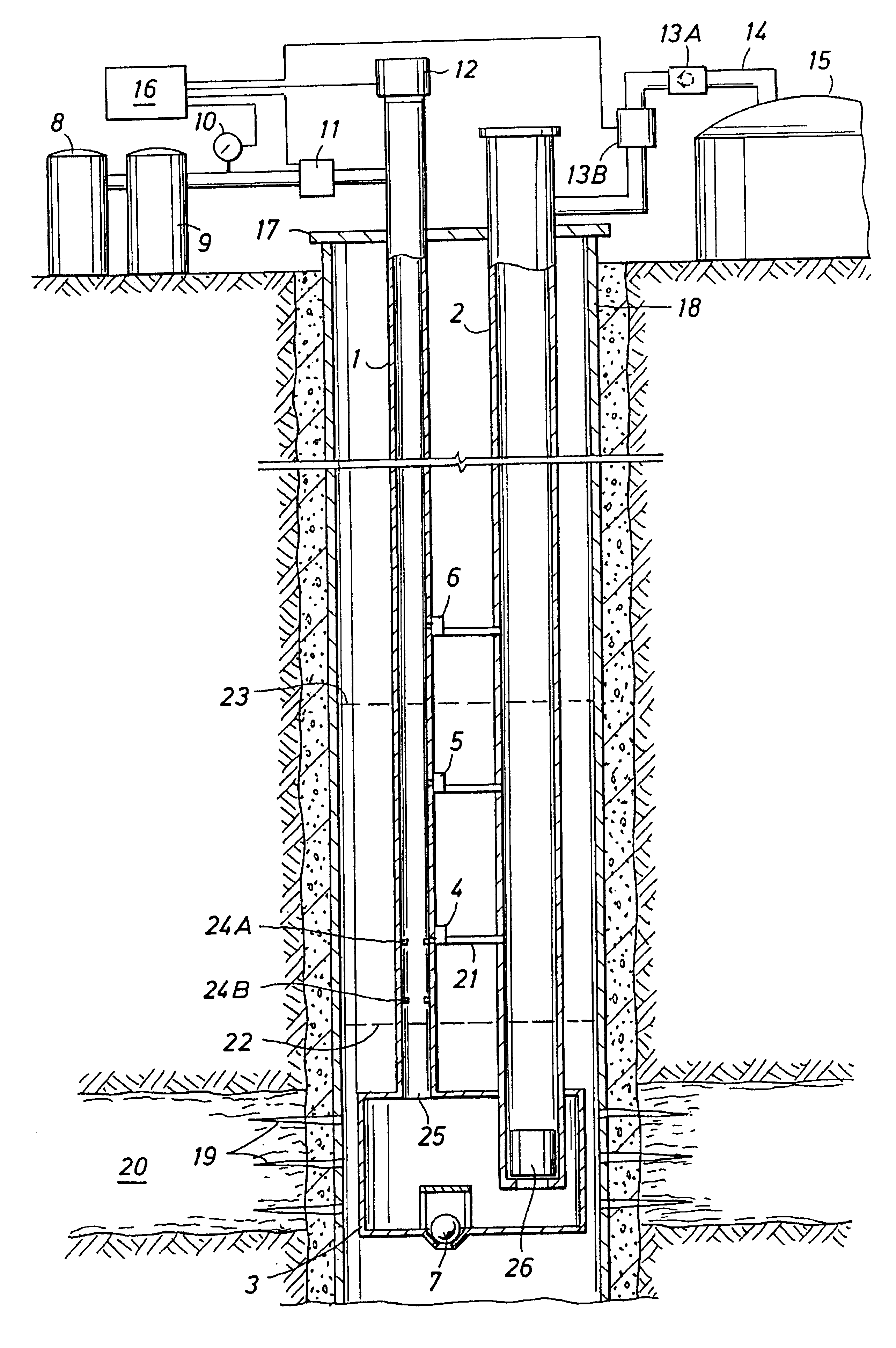
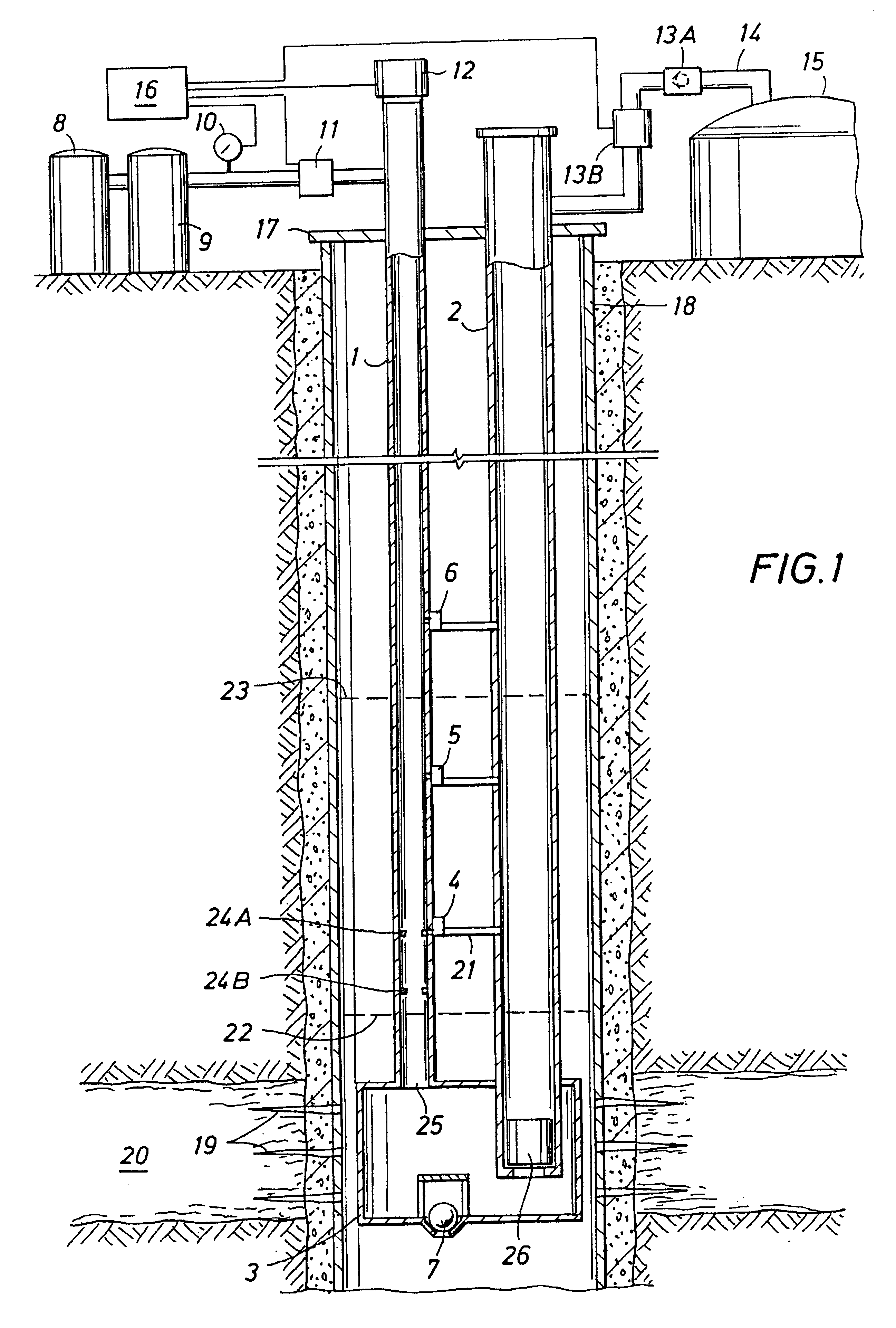
Consider the unlikely event where the liquid rises 700 feet above the bottom of the second tube (liquid discharge line) 2 and the liquid will be in the first tube (gas line) 1, and 12 gallons of liquid is in the accumulator (pump tank) 3. Assume the first bypass 4 is 100 feet above the bottom of the liquid discharge line 2, and the spacing between each of the higher bypasses is 300 feet. Upon applying 180 psi to the gas line, the liquid rises in the second tube (oil / water) line such that the height is 180 psi.times.37.5 feet oil / 14.7 psi=459 feet above the level in the first tube 1. Since again for each two feet that the liquid goes down in the first tube (gas line) 1, the liquid rises one foot in the second tube (oil line)(2); therefore, the liquid level in the second tube will now be (153 feet plus 700 feet) 853 feet above the bottom of the second tube (oil / water line) 2. When the applied pressure reaches 180 psig (194.7 psia), valve 4 will open but the system can not pump the liq...


PUM


Abstract

An intermittent gas lift well pumping system containing an accumulator, a gas line, a liquid discharge line, and a battery operated controller. By using one or more constrictions in the gas line and acoustical techniques, accurate liquid level is determined in the pumping system for optimum production. Bypasses are connected between the gas line and the liquid discharge line. Each contains a valve that opens at a preset absolute pressure in the gas line, an orifice, and a one-way valve. The bypasses are strategically placed to prevent overloading of the system. A liquid slug sensor on the upper end of the liquid discharge line and a rabbit in this line enables optimum production and gas conservation.

Description

1. Field of the InventionThis invention pertains to pumping liquids from a well in the earth. More particularly, method and apparatus are provided for controlled gas lift system to pump liquid from a well.2. Description of Related ArtGas lift systems are used in the initial production of many oil and gas wells and are excellent systems to employ when the gas supply and reservoir pressure are adequate to produce the liquid in a gas conserving manner. After reduction of the reservoir gas pressure and thus the reservoir supply, one usually has to make a decision concerning the method of pumping when the reservoir pressure is not sufficient for economical regular gas lift to continue. Intermittent gas lift systems are often employed rather than beam pumps because of their flexibility, low initial capital cost per well pump, low operational costs, and economical use of gas in the lift. For example, the energy costs for the inventor's system pumping a shallow well at a depth of 1400 feet ...

Claims


Application Information

Patent Timeline
IPC IPC(8): E21B43/12E21B47/04
CPCE21B47/042E21B43/122E21B47/047
Inventor BUCKMAN, SR., WILLIAM G.
Owner BUCKMAN SR WILLIAM G
Why Eureka
Try Eureka