
Line type illuminator

a technology of illuminator and light source, applied in the field of illuminator, can solve the problems of large number of leds needed to be installed, significant lack of evenness in the intensity of illumination, and lack of ligh

Inactive Publication Date: 2002-03-19
NIPPON SHEET GLASS CO LTD
View PDF12 Cites 90 Cited by
  • Summary
  • Abstract
  • Description
  • Claims
  • Application Information

AI Technical Summary

Benefits of technology

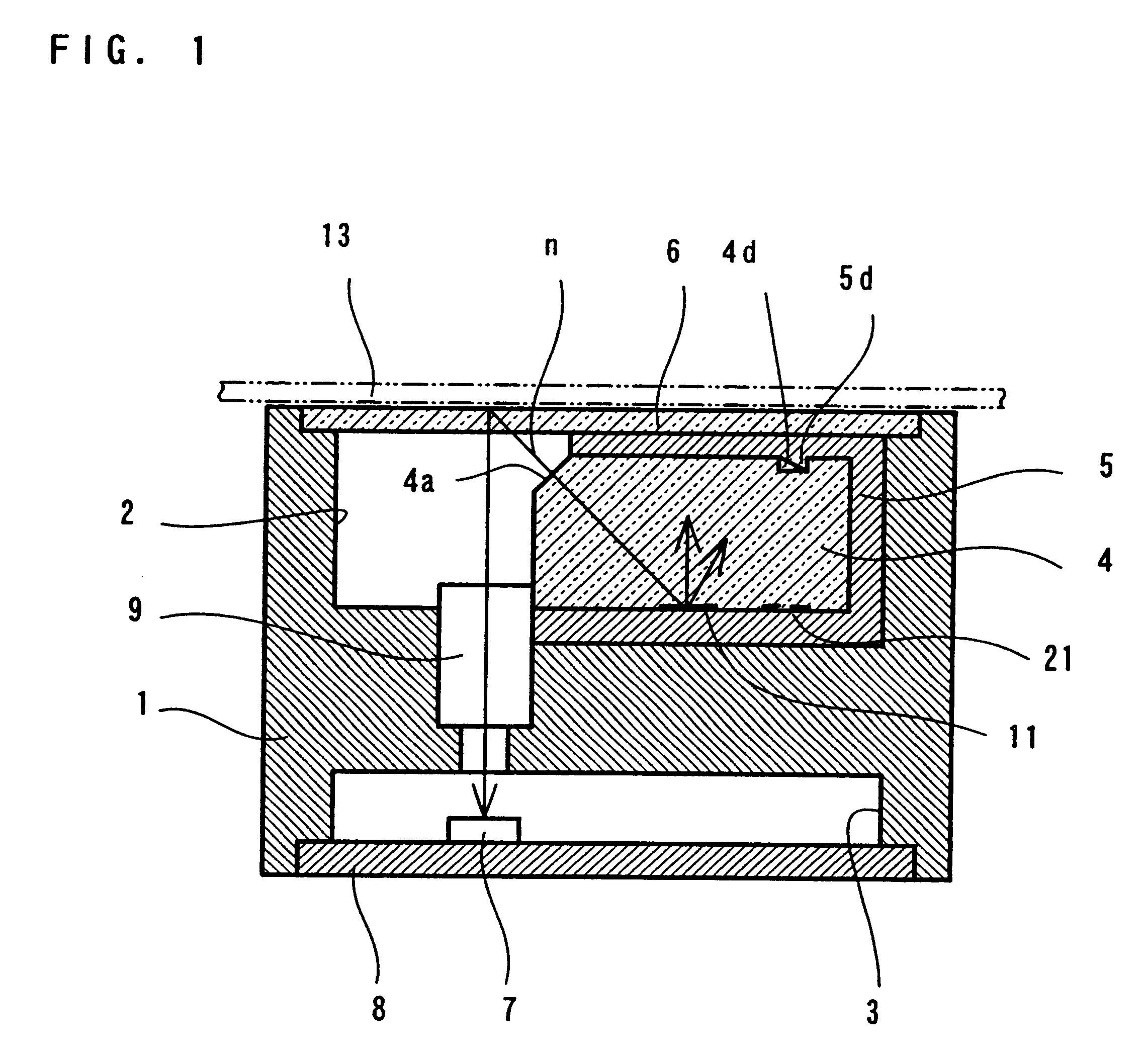
Also, according to the present invention, the other end surface of the above-mentioned rod-like transparent light guide may have a rough surface. Such a rough surface can be manufactured with ease, however the light incident upon the rough end surface is hardly reflected because of the rough surface thereof. A white paint is therefore applied upon the rough surface to reflect light more effectively, thereby obtaining a further utilization of the light emitted by the light sources.
With such a construction, it is possible to maintain a high intensity of illumination, and a high degree of evenness or uniformity thereof as well.
Further, according to the present invention, the first portion of said main light scattering pattern mentioned above may be formed with a portion in which light scattering patterns are formed discontinuously or spattered, and with another portion in which the light scattering patterns are formed continuously. In particular, in a case where the engaging portion in the concave and convex shape is formed in a portion of the rod-like transparent light guide, with the provision of a pattern omission portion corresponding to the concave and convex engaging portion, it is possible to maintain evenness of illumination.

Problems solved by technology

Also, there is a method in which the illuminator is brought to be as close as possible to the manuscript to be read, to make the intensity of illumination of the line of the manuscript as bright as possible, thereby to reduce the number of the LEDs necessary to be installed, however in such a case there occurs a significant lack of evenness in the intensity of illumination.
Also, in the illuminator having such a structure, there occurs a lack of evenness in the amount of light in a degree varying with a pitch of mounting of the LEDs.
Further, inadequate uniformity may occur in the relative brightness of the individual LEDs used due to non-uniformity in the manufacturing thereof.
Accordingly, if the number of the LEDs mounted onto an illuminator is reduced, the unevenness of the intensity and distribution of light emitted upon the reading line of the manuscript to be read becomes large.
However, with the line type illuminator mentioned in the above, inherent problems of reading of, in particular, a color manuscript, have not been studied.
As the LED chips are of insubstantial size, it is therefore impossible to position them at substantially the same position.

Method used


Image

  • Line type illuminator
  • Line type illuminator
  • Line type illuminator

Examples


Embodiment Construction

The condition of the experiments is as follows:

Auxiliary light scanning pattern: no;

Total length of the light scanning pattern: 172.8 mm; and

Intensity of illumination of incident lights: 650 .mu.W.

Evaluations

In FIG. 10, as in FIG. 9, the vertical axis indicates the relative intensity of illumination (V: voltage), while the horizontal axis the distance of the light scattering pattern from the light source. Regarding the red-color light source, the relative intensity of illumination is 1.801 V at the maximum value thereof and 1.463 V at the minimum value, and the average value thereof is 1.590 V; with the green-color light source, the relative intensity of illumination is 2.053 V at the maximum value and is 1.673 V at the minimum value, and the average value thereof is 1.851 V; and with the blue-color light source, the relative intensity of illumination is 1.522 V at the maximum value and is 1.188 V at the minimum value, and the average value thereof is 1.306 V.

As shown in FIG. 10, ev...


PUM


Abstract

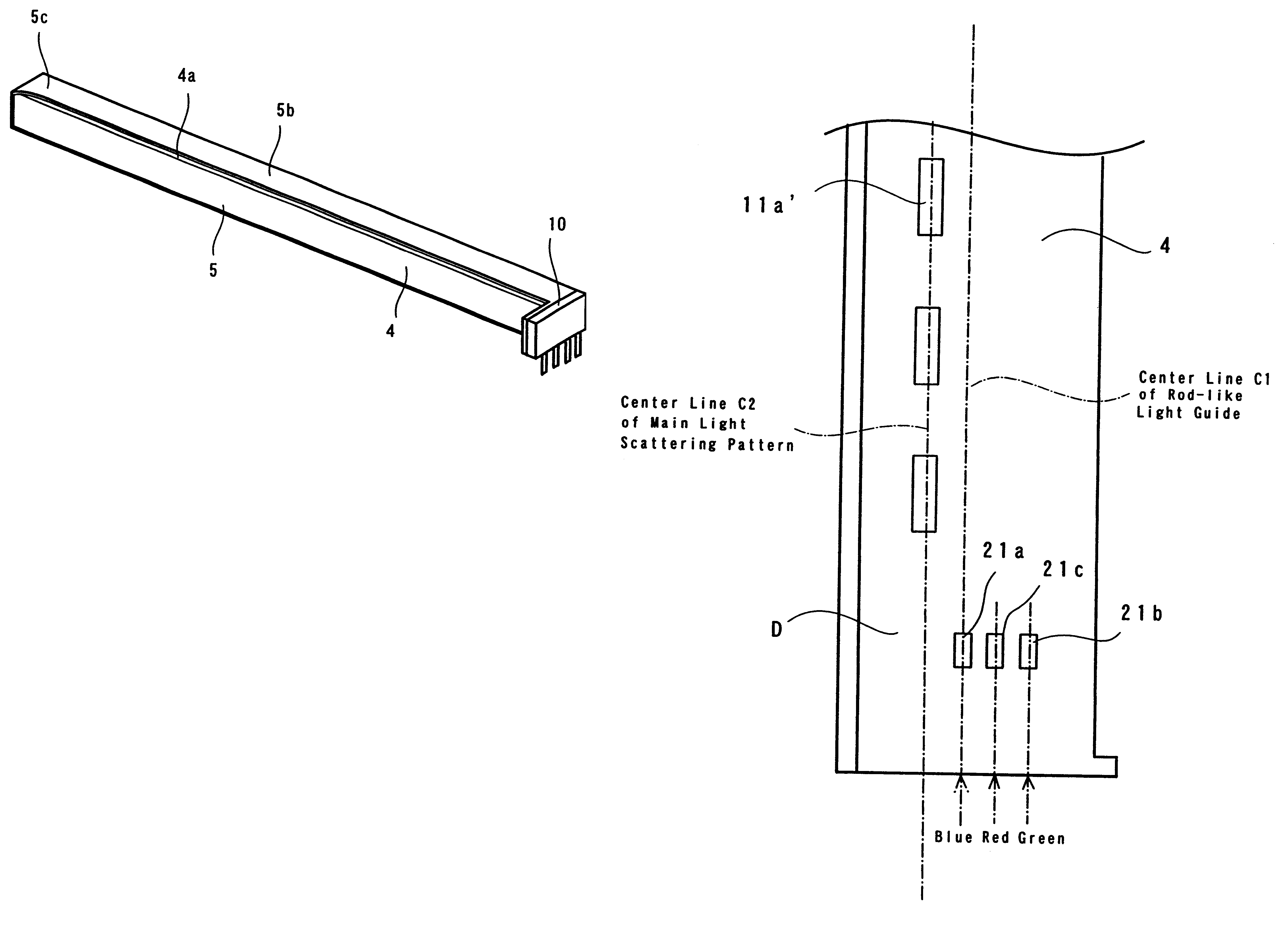
A line type illuminator comprising a plurality of light sources at a side of one end of a rod-like transparent light guide, wherein an auxiliary light scattering pattern is formed with two (2) spot-like patterns, which are provided at positions being shifted from a center line of a main light scattering pattern in the longitudinal direction and are separate in a width direction, for maintaining evenness or uniformity of illumination intensity in a longitudinal direction. Normal lines of those two (2) spot-like patterns and the center line of any one of the plurality of light sources, extending in the longitudinal direction, intersect each other. Specifically, the longitudinal center lines of the red-color light sources and the green-color light source intersect the respective normal lines of the spot-like patterns 21a and 21a.

Description

1. Field of the InventionThe present invention relates to an illuminator of a line type to be used in or installed into an image reading apparatus for use in, for example, a facsimile machine, a copy machine, an image scanner, etc.2. Description of Related ArtIn machines such as facsimile machines, copy machines, image scanners, etc., as a device for reading a manuscript or image, there is applied an image reading apparatus, such as an image sensor, etc. Known types of image sensors are, for example, the reduced type, the close-contact type, the full-contact type, etc. Among them, image sensors of the contact type are normally constructed with an illuminator, an optical device of an equal power for imaging or equimultiple imaging, a sensor, and so on.The image sensor of the close-contact type, in general, has a short light path, compared to that of the image sensor of the reduced type, thereby allowing for an apparatus of small size, and rendering unnecessary any troublesome optical...

Claims


Application Information

Patent Timeline
Patent Type & Authority Patents(United States)
IPC IPC(8): H04N1/028H04N1/04G03B27/54
CPCH04N1/02815H04N1/0289H04N1/02835Y10S362/80
Inventor FURUSAWA, SATOSHISAITO, TOMIHISA
Owner NIPPON SHEET GLASS CO LTD
Learn More