Cowling arrangement for outboard motor

a technology for outboard motors and cowling, applied in the field of cowling, can solve problems such as damage to the throttle device and/or the failure of the throttle devi

Inactive Publication Date: 2002-03-19
SANSHIN KOGYO CO LTD
View PDF24 Cites 13 Cited by
  • Summary
  • Abstract
  • Description
  • Claims
  • Application Information

AI Technical Summary

Benefits of technology

In a preferred embodiment, the cowling includes a flywheel cover which substantially covers the upper surface of the flywheel and engine. A rib is formed in a portion of the flywheel cover near the throttle body. This rib extends upwards and prevents water splashing into the engine compartment from splashing on the throttle body. Moreover, this rib redirects air passing over the flywheel cover near the throttle body, acting as a labyrinth, which tends to remove water suspended in the air which passes over the throttle body. In addition, a downwardly extending rib extending from the cowling towards the flywheel cover further prevents splashing of water and further redirects the air flowing towards the throttle body.
If desired, a gutter can be formed in the flywheel cover. The gutter provides a channel for draining water off the flywheel cover, thereby preventing pooled water from draining on the throttle body during watercraft turns. In addition, where air guide chamber is narrow, such as where there is little separation between the flywheel cover and the cowling, the addition of a gutter to the flywheel cover can significantly increase the effective height of the rib, thereby permitting more water to be removed from the air before it passes over the throttle body.
In another preferred embodiment, the rib extending downward from the cowling is formed in a continuous L-shape, which further reduces the possibility that splashing water will contact the throttle body, and reduces the chance that water condensing on the dividing wall section of the cowling will subsequently travel over and drip onto the throttle body.

Problems solved by technology

However, when water splashes into the air vent, it can flow through the air guide chamber and deposit on the throttle body, often resulting in malfunctioning of and / or damage to the throttle device.
In addition, during watercraft turns, any water that pools on the flywheel cover can often drain onto the throttle body.

Method used


Image

  • Cowling arrangement for outboard motor
  • Cowling arrangement for outboard motor
  • Cowling arrangement for outboard motor

Examples


Embodiment Construction

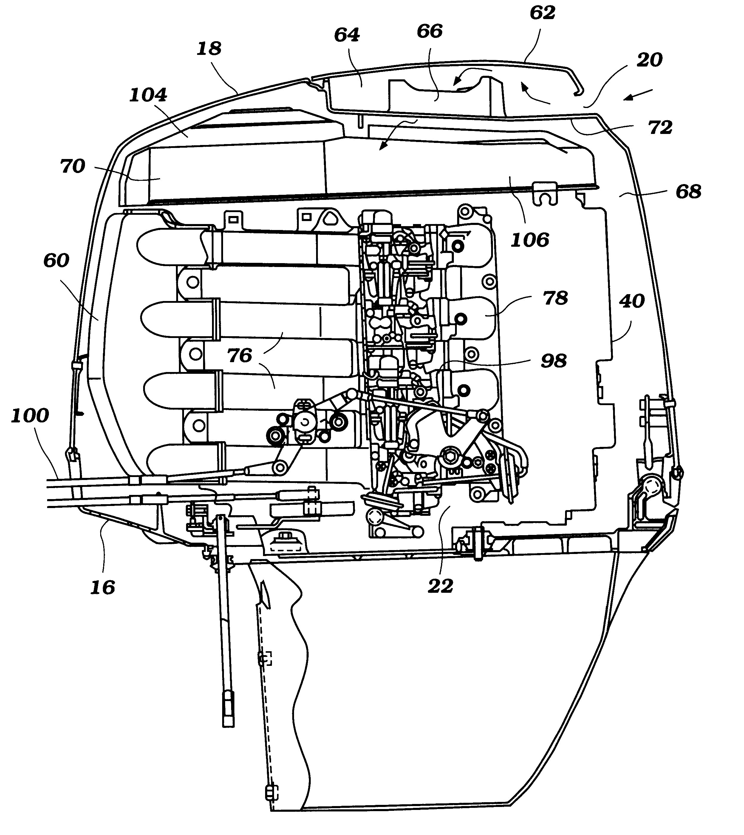
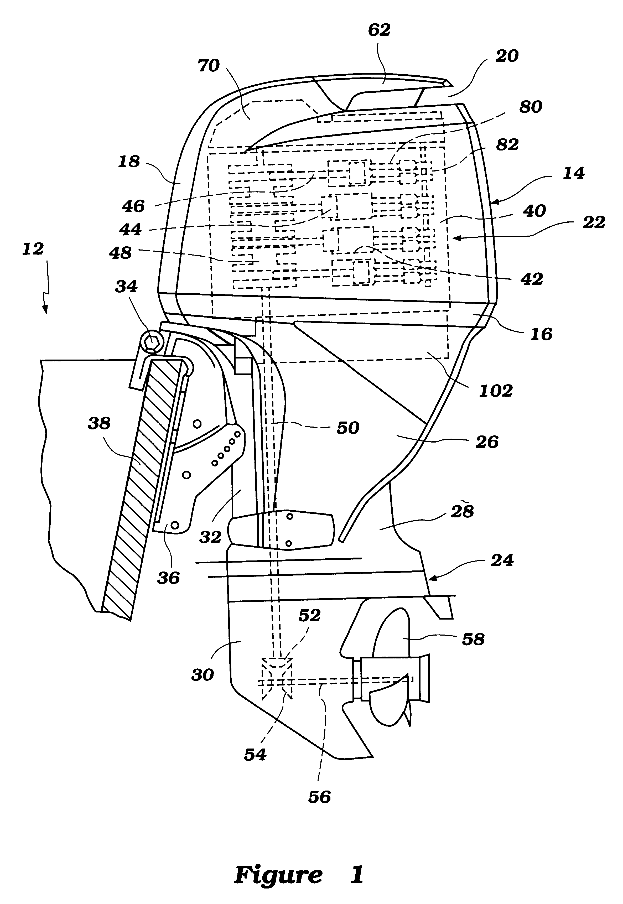
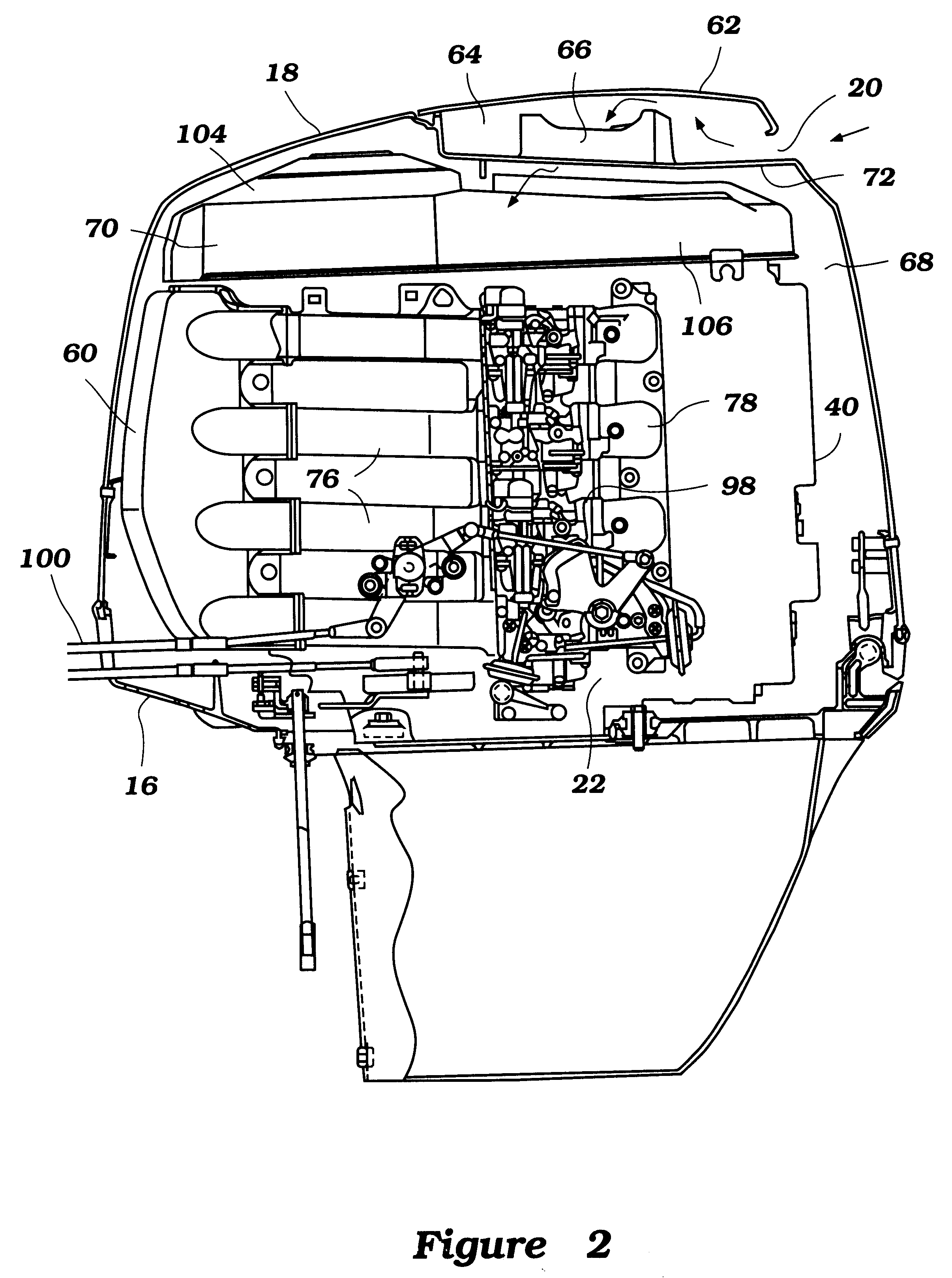
With reference to FIG. 1, the outboard motor 10 is utilized to power a watercraft 12. The outboard motor 10 has a power head area 14 comprised of a lower tray portion 16 and a main cowling portion 18. An air inlet or vent 20 is provided in the main cowling portion 18 for providing air to an engine 22 therein, as described in more detail below. The motor 10 includes a lower unit 24 extending downwardly therefrom, with an apron 26 providing a transition between the powerhead 14 and the lower unit 24. The lower unit 24 comprises an upper or "drive shaft housing" section 28 and a lower section 30.

A steering shaft (not shown) is affixed to the lower section 30 of the lower unit 24 by means of a bracket (not shown). The steering shaft is supported for steering movement about a vertically extending axis within a swivel bracket 32. The swivel bracket 32 is connected by means of a pivot pin 34 to a clamping bracket 36 which is attached to the transom 38 of the watercraft 12. The pivot pin 34...


PUM


Abstract

An improved cowling arrangement for an outboard motor powered by an internal combustion engine. The improved arrangement includes a flywheel cover and cowling that incorporate upwardly and downwardly extending ribs which are positioned along an air path between the air vent of the outboard motor and the throttle body of the motor. These ribs act as labyrinth-type seals which prevent water entering the air vent from contacting the throttle body. Also disclosed is an improved cowling arrangement that prevents water pooled on the flywheel cover from draining onto the throttle body when the motor is tilted, such as when the watercraft banks into a turn.

Description

This application is based on and claims priority to Japanese Patent Application No. 10-114430, which was filed on Apr. 24, 1998.1. Field of the InventionThe present invention generally relates to an outboard motor for use with a watercraft. More specifically, the present invention relates to a cowling for an outboard motor powered by an internal combustion engine.2. Description of Related ArtOutboard motors are often powered by internal combustion engines. The engine is typically positioned within an enclosed cowling. The engine is generally vertically arranged, so that a crankshaft thereof may extend downwardly in driving relation with a water propulsion device of the motor, such as a propeller. In order to balance the motor and because of space considerations, the engine is arranged with a crankcase of the engine facing in the direction of a watercraft to which the motor is mounted (i.e., positioned on a front side of the engine), and with the cylinder head positioned on an end of...

Claims


Application Information

Patent Timeline
Patent Type & Authority Patents(United States)
IPC IPC(8): F02B75/20F02B75/00F02B61/00F02B61/04F02M35/00F02M35/16F02B75/02F02B75/18B63H20/00
CPCF02B61/045F02B75/20F02M35/10013F02M35/112F02M35/168F02B2075/027Y02T10/14F02B2075/1816Y02T10/12
Inventor ISOGAWA, ATSUSHIISHIDA, HITOSHI
Owner SANSHIN KOGYO CO LTD
Why Eureka
Try Eureka