
Multicombination vehicle and method for transporting a payload in an underground mine

Inactive Publication Date: 2002-03-26
COOPER JAMES W
View PDF31 Cites 20 Cited by
  • Summary
  • Abstract
  • Description
  • Claims
  • Application Information

AI Technical Summary

Benefits of technology

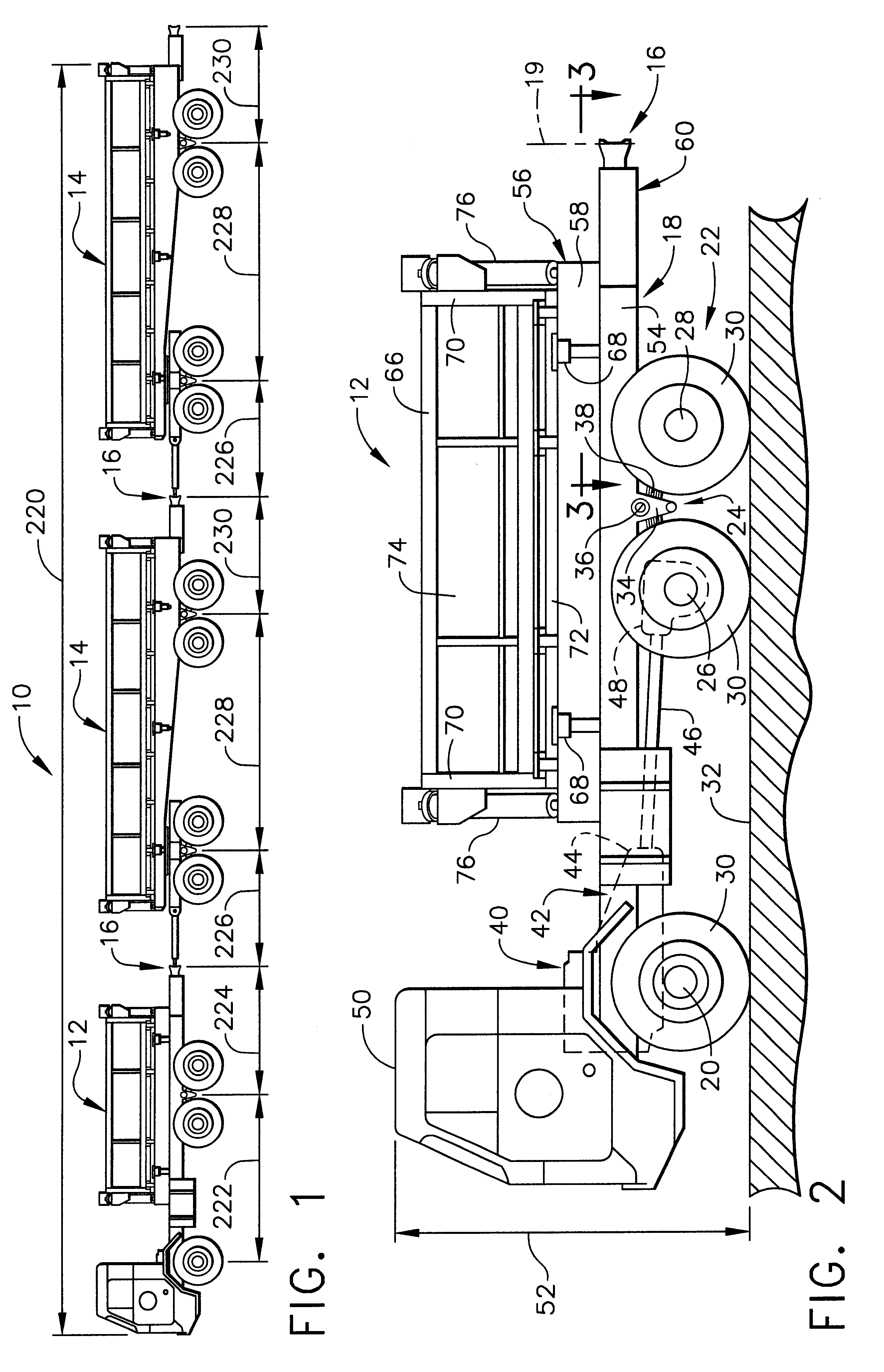
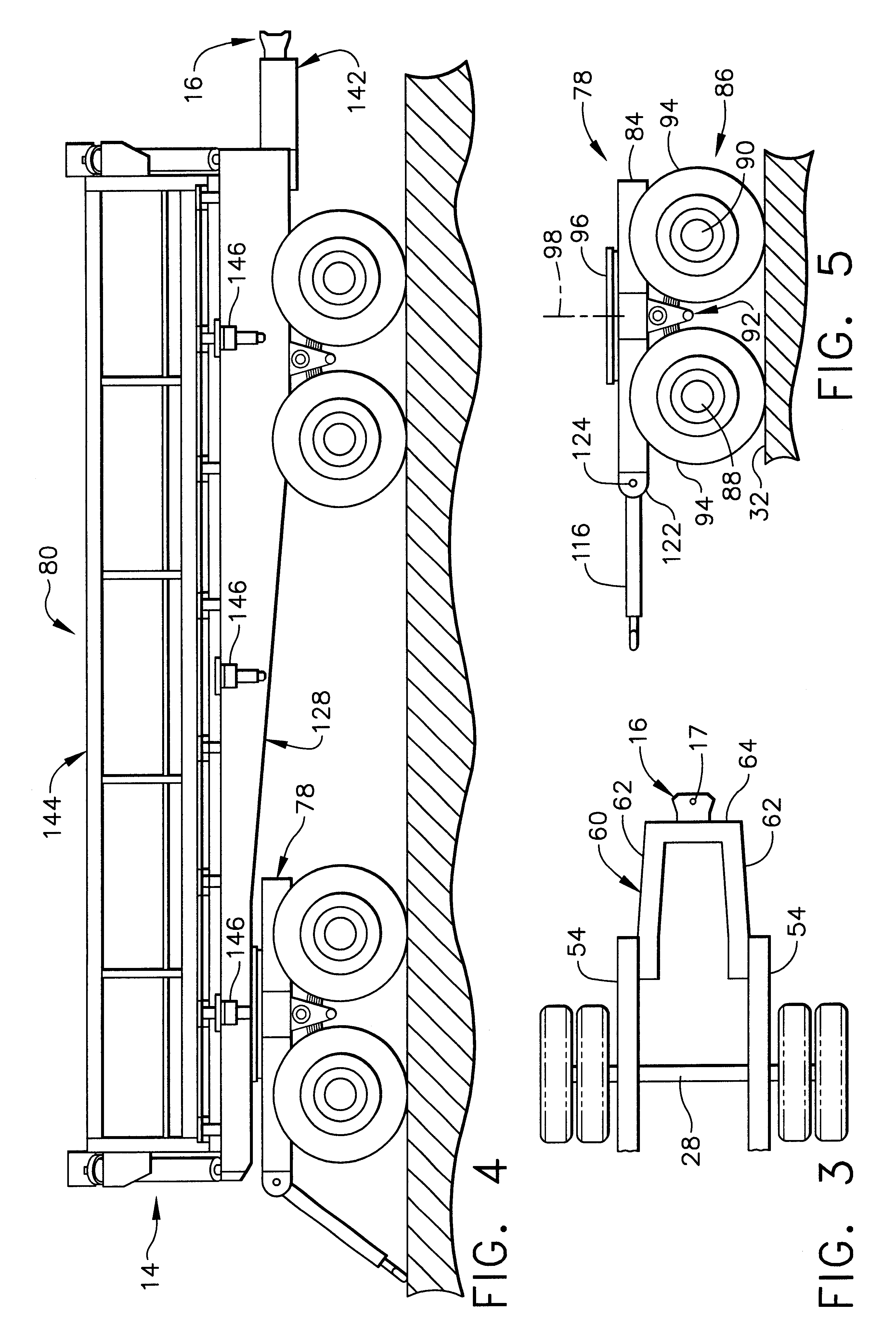
According to a second aspect of the present invention, a method is provided for transporting a mined payload over the roadways existing in an underground mine. According to a preferred embodiment, the method comprises the steps of providing a multicombination vehicle having a powered towing unit and at least one towed unit, with each adjacent pair of units being mechanically coupled to one another, and each of the units including a load-carrying body. The method further includes the steps of minimizing a swept path width of the multicombination vehicle as the vehicle travels over the roadways of the underground mine, loading pre-determined quantities of the payload into the load-carrying bodies of each of the units of the vehicle, driving the vehicle over at least one of the roadways to a payload-dumping area, and dumping the payload from the load-carrying bodies of each of the units into a receptacle disposed in the payload-dumping area.
The step of minimizing the swept path width may include the steps of establishing a ratio of the coupling overhang to the wheelbase of at least 0.5, for each unit of the vehicle, and configuring each of the towed units so that the dolly drawbar length of each of the towed units has a value less than 3.0 meters.

Problems solved by technology

An underground railway system is relatively expensive to install and operate due to the cost of acquiring the locomotive and installing the fixed railway system and the associated maintenance costs.
Furthermore, and perhaps more importantly, an underground railway system is route-specific and therefore not flexible to changes in route without incurring the expense of installing additional railway tracks.
A single ore crusher and associated shaft is typically used due to the prohibitive costs associated with drilling a shaft from the surface to the mining area deep below the ground.
As each new mining area opens, it is necessary to incur the cost of installing new track for the railway system, or to use supplemental vehicles to haul the ore from the mining area to the end of the railway track system.
However, known trucks of this type are typically designed for hauling loads over relatively short distances and rough terrain, such as that which may be experienced in above-ground applications.
Accordingly, such trucks are typically designed with relatively large tires for relatively slow speed operation and are relatively expensive to operate and maintain due to fuel and tire costs.
However, conventional "road trains" are typically designed for use at relatively high speed, for instance at speeds up to 55-60 mph, and are therefore not capable of operating in an underground mine for the following reasons.
This location of mechanical couplings between each adjacent pair of vehicles is required to maintain the side-to-side sway, or yaw, of the last vehicle within acceptable limits for aboveground, over-the-road application, but is not compatible for operation within an underground mine due to the relatively low operating speeds as well as the relatively narrow tunnels and small radius bends experienced in underground mines.

Method used


Image

  • Multicombination vehicle and method for transporting a payload in an underground mine
  • Multicombination vehicle and method for transporting a payload in an underground mine
  • Multicombination vehicle and method for transporting a payload in an underground mine

Examples


Embodiment Construction

The inventor has conducted additional swept path width, computer-aided analysis which demonstrates the reduction in swept path width which may be achieved by the multicombination vehicle 10 of the present invention as compared to known vehicles having a similar configuration with the exception that the known vehicles do not include the draw frames 60 and 142 as described previously. For purposes of this example, the various values of the multicombination vehicle 10 discussed above had the following values:

wheelbase 222 of truck 12=4.27 m (168");

coupling overhang 224 of truck 12=2.46 m (97");

dolly drawbar length 226 of each towed unit 14=2.46 m (97");

wheelbase 228 of each towed unit 14=4.97 m (196");

coupling overhang 230 of each towed unit 14=2.46 m (97");

overall length of vehicle 10=27 m (1062")

The comparison vehicle had the same overall length. The comparison vehicle did not include draw frame 60 of truck 12 or draw frames 142 of towed units 14 and had a dolly drawbar length of 3.1...


PUM


Abstract

A multicombination vehicle and method are provided for transporting a payload, such as a mined metal ore, over the roadways existing in an underground mine. The multicombination vehicle includes a powered towing unit, which may comprise a rigid body truck, and at least one towed unit mechanically coupled to the rigid body truck. The vehicle may also include a plurality of the towed units, with a forward most one of the units coupled to the rigid body truck and each adjacent pair of the towed units being coupled to one another. Each of the units includes a chassis, a plurality of wheeled axles connected to the chassis for supporting the respective unit as the vehicle travels over the roadways of the mine, and a draw frame attached to and extending rearwardly from the corresponding chassis, with a coupling attached to a rear end of the draw frame. Each towed unit may comprise a semi-trailer mounted on a dolly, with a drawbar attached to and extending forwardly from the dolly and connected with the coupling of the immediately forward unit of the vehicle. The multicombination vehicle is configured so as to minimize the swept path width of the vehicle as the vehicle negotiates turns. This is accomplished by providing each of the towed units with a dolly drawbar length having a value of less than 3.0 meters and establishing a ratio of the coupling overhang-to-wheelbase, for each of the units, of at least 0.5.

Description

1. Field of the InventionThe present invention is directed to vehicles for transporting a payload and, more particularly, to a multicombination vehicle for transporting a payload, such as a mined ore, over the roadways in an underground mine. The multicombination vehicle includes at least one powered, load-carrying towing unit and at least one load-carrying towed unit. The multicombination vehicle is configured to minimize the swept path width of the vehicle to permit operation within the relatively narrow tunnels and included relatively low radius turns typically found in underground mines.2. Related ArtMined payloads, such as various metal ores, are typically transported through the tunnels of an underground mine by either a railway train including a locomotive and one or more cars operating on a fixed system of railway tracks, or rigid body, load-carrying trucks. Although each known system may be advantageously utilized in certain applications, they are both subject to various di...

Claims


Application Information

Patent Timeline
IPC IPC(8): B60P1/04B60P1/16
CPCB60P1/165
Inventor COOPER, JAMES W.
Owner COOPER JAMES W
Learn More