Release oil regulating blade, fixing device, and image-forming apparatus

Inactive Publication Date: 2002-03-26
CANON KK
View PDF6 Cites 1 Cited by
  • Summary
  • Abstract
  • Description
  • Claims
  • Application Information

AI Technical Summary

Problems solved by technology

In particular, recently, since the amount of coating of the release oil has been reduced, even slight nonuniformity of the release oil may deteriorate the image qu

Method used


Image

  • Release oil regulating blade, fixing device, and image-forming apparatus
  • Release oil regulating blade, fixing device, and image-forming apparatus
  • Release oil regulating blade, fixing device, and image-forming apparatus

Examples


example 1

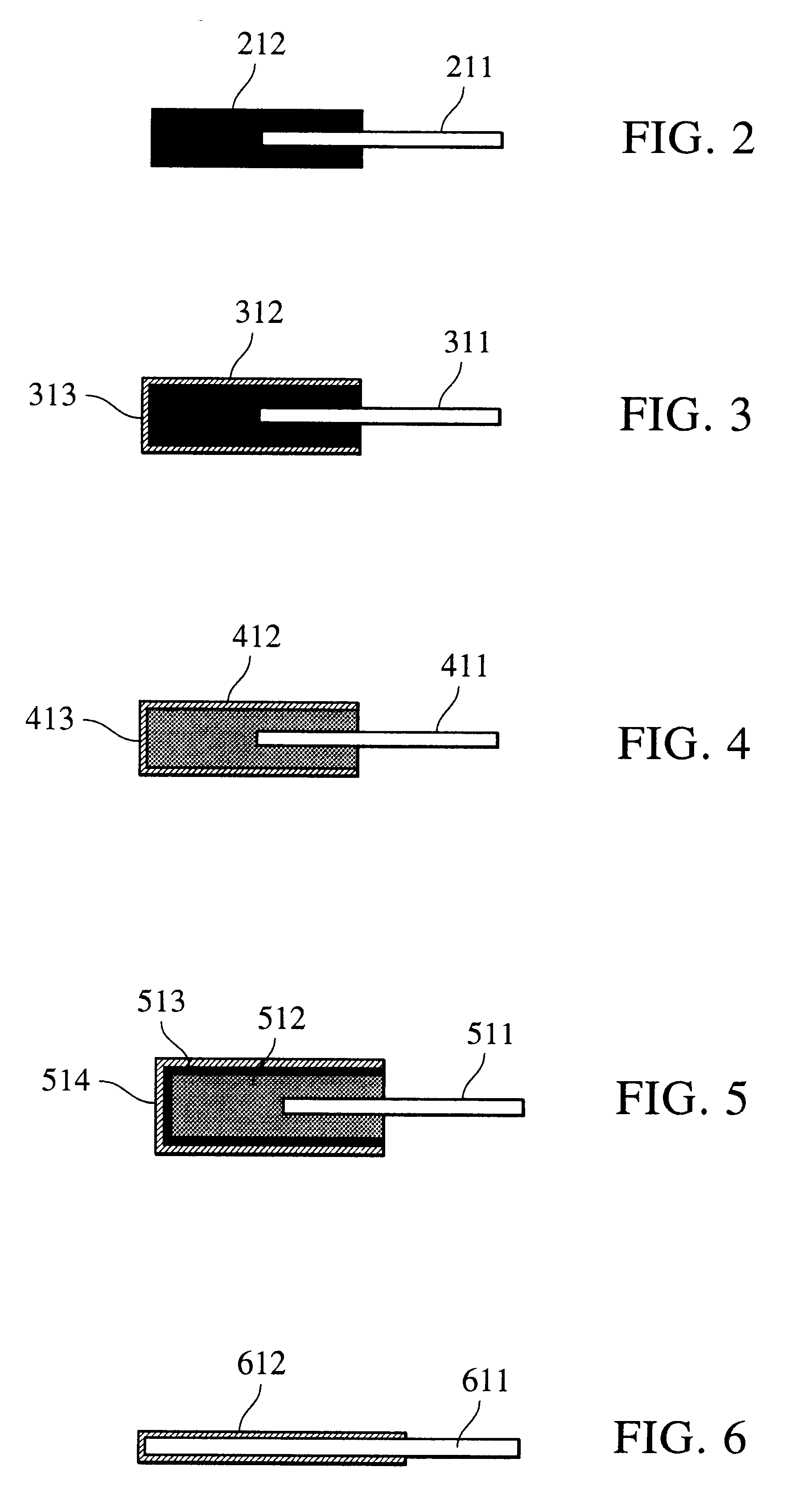
A fluororubber blade was produced by vulcanizing and molding a fluororubber polymer (trade name "DAI-EL G-723" manufactured by Daikin Industries, Ltd.). The entire surface of the fluororubber section of the fluororubber blade was subjected to primer treatment, and a toluene-diluted silicone rubber solution was sprayed thereon so as to have a thickness of approximately 40 .mu.m after evaporation of the toluene, followed by standing at room temperature for 30 minutes in order to evaporate the toluene. Next, in a hot-air furnace, primary curing was performed at 130.degree. C. for 1 hour, and then secondary curing was performed at 200.degree. C. for 4 hours to obtain a blade. FIG. 3 is a schematic diagram showing a cross section of the blade in Example 1. The blade includes a metallic plate 311 as a support, a fluororubber layer 312 as an elastic layer formed on the metallic plate 311, and a silicone rubber layer 313 formed on the surface thereof.

example 2

A silicone rubber blade was produced by molding, vulcanizing, and bonding a silicone rubber (trade name "DY32-916u" manufactured by Dow Corning Toray Silicone Co., Ltd.) so as to have the same shape as that of the fluororubber layer of the fluororubber blade in Example 1. Next, the entire surface of the silicone rubber blade was subjected to primer treatment, and a toluene-diluted silicone rubber solution was sprayed thereon so as to have a thickness of approximately 20 .mu.m after evaporation of the toluene, followed by standing at room temperature for 30 minutes in order to evaporate the toluene. In a hot-air furnace, primary curing was performed at 130.degree. C. for 1 hour, and then secondary curing was performed at 200.degree. C. for 4 hours to obtain a blade. FIG. 4 is a schematic diagram showing a cross section of the blade in Example 2. The blade includes a metallic plate 411 as a support, a silicone rubber layer (lower layer) 412 as an elastic layer formed on the metallic p...

example 3

A silicone rubber blade was produced by molding, vulcanizing, and bonding a silicone rubber (trade name "DY32-916u" manufactured by Dow Corning Toray Silicone Co., Ltd.) so as to have the same shape as that of the fluororubber layer of the fluororubber blade in Example 1. Next, the entire surface of the silicone rubber blade was subjected to primer treatment, and a polyamine-based fluororubber latex (trade name "DAI-EL GL-252" manufactured by Daikin Industries, Ltd.) was sprayed thereon so as to have a thickness of approximately 40 .mu.m after drying, followed by drying at 50.degree. C. for 30 minutes. A primer was applied thereto, and heat treatment was performed for 60 minutes at 200.degree. C. in a hot-air furnace to cure the fluororubber layer as well as to modify the primer on the surface of the fluororubber layer. Primer treatment was performed again, and a toluene-diluted silicone rubber solution was sprayed so as to have a thickness of approximately 20 .mu.m after evaporatio...


PUM


Abstract

A blade for regulating the amount of a release oil to be supplied is placed so as to abut on a fixing member or on a member for controlling the amount of the release oil to be supplied to the fixing member. The abutting surface of the blade is composed of a silicone rubber layer. Alternatively, the blade includes a plate-shaped elastic body and a silicone rubber layer formed on the tip of the elastic body. A fixing device including the blade and an image-forming apparatus including the fixing device are also disclosed.

Description

1. Field of the InventionThe present invention relates to a blade for regulating a release oil used in fixing devices, such as those used in electrophotographic copying machines and printers, and also relates to a fixing device for performing heat-pressure fixing of an unfixed image by passing a recording member carrying the unfixed image between fixing members which are in contact with each other under pressure, and to an image-forming apparatus.2. Description of the Related ArtIn a fixing apparatus, such as those used in an electrophotographic copying machine or printer, in general, a fixing roller and a pressure roller, which are heated by halogen heaters or the like, are brought into contact with each other under pressure, and a recording sheet carrying a toner image is transported through the nip to fix the toner image on the recording sheet. Instead of the fixing roller, a fixing belt or a fixing film may be used. Such members for fixing toner are referred to as fixing members...

Claims


Application Information

Patent Timeline
IPC IPC(8): G03G15/20
CPCG03G15/2025G03G2215/2093
Inventor ISHIZUKA, JIROKISHINO, KAZUOTAKAHASHI, MASAAKIKAWAMOTO, HIDEOOTA, MITSUHIROSOUTOME, OSAMUKITANO, YUJI
Owner CANON KK
Why Eureka
Try Eureka