Adder circuit with the ability to detect zero when rounding

a technology of adder circuit and zero, applied in the field of digital processing, can solve the problems of large time delay add and carry, add and carry process, etc., and achieve the effect of reducing the time delay

Inactive Publication Date: 2002-04-02
SILICON SYST LTD +1
View PDF7 Cites 45 Cited by
  • Summary
  • Abstract
  • Description
  • Claims
  • Application Information

AI Technical Summary

Problems solved by technology

This add and carry, add and carry, add and carry process takes considerable time (called a propagation delay).
In the situation where an adder must perform a rounding operation, the time delay can become very significant.
This operation is usually performed by an AND operation which provides additional time delays to the ALU operations.

Method used


Image

  • Adder circuit with the ability to detect zero when rounding
  • Adder circuit with the ability to detect zero when rounding
  • Adder circuit with the ability to detect zero when rounding

Examples


Embodiment Construction

The present invention provides an adder circuit having a zero detecting reworking circuit. By providing the ability to detect zero when rounding, the present invention gives adder circuits the ability to realize the time savings afforded by ignoring the add operations and proceed directly to the next operation when the combination of the two operands is equal to zero.

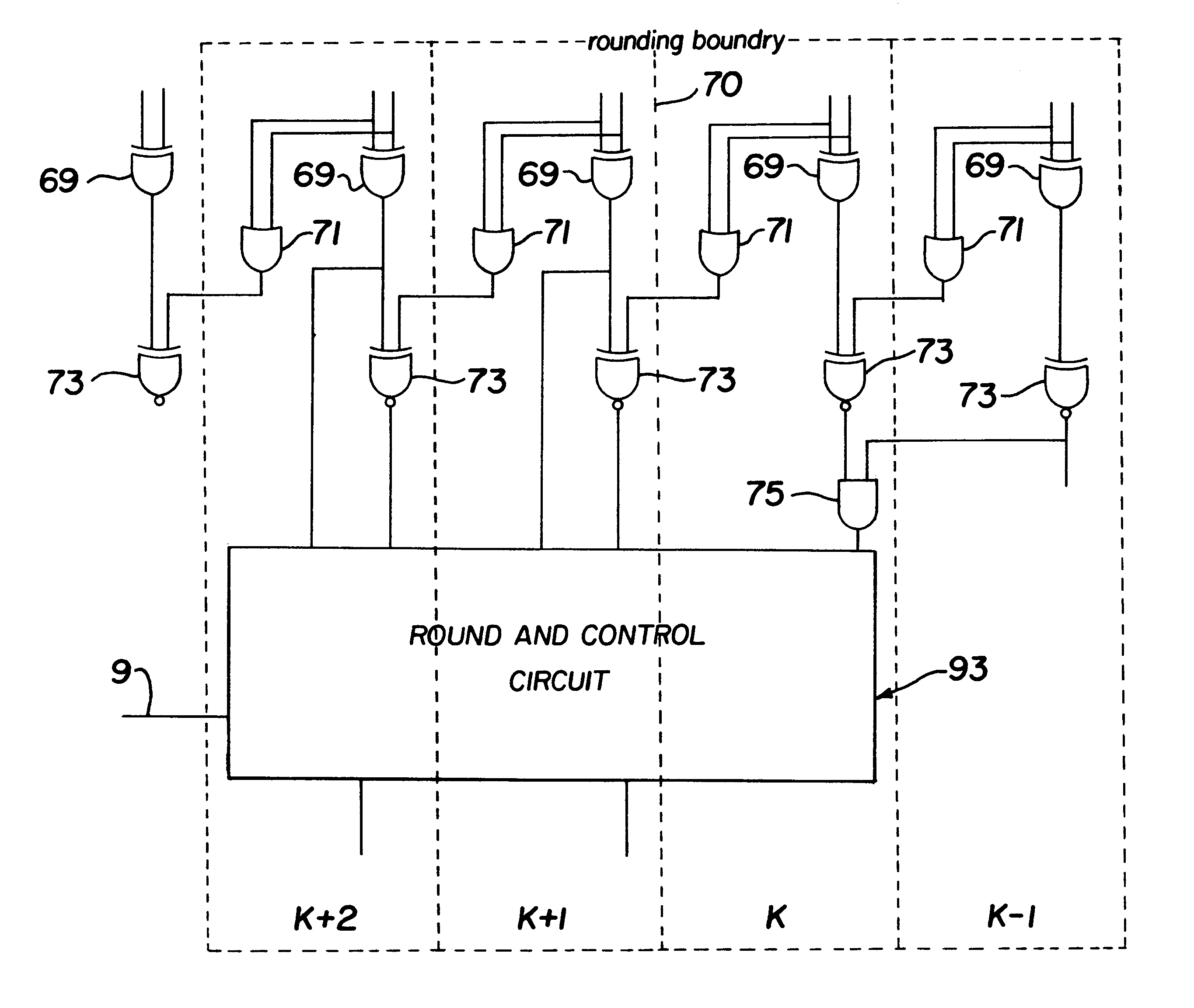
Turning now to FIG. 1, there is shown a block diagram of a multiply and accumulator unit (MAC) 100 constructed according to the invention. The multiply and accumulator circuit 100 includes a register 1 where an operand A is stored prior to being applied to the Booth decoder 5 and a register 3 where a operand B is stored prior to being applied to the Booth decoder 5. It is preferred that register 1 and register 3 operate on 56 bits and operand A and operand B consist of 56 bits.

The Booth decoder 5 receives operand A from register 1 and operand B is received from register 3, and manipulates them to produce a partial produ...


PUM


Abstract

An adder circuit uses a summing circuit to provide a summed sliced bit number from a first sliced bit number and a second sliced bit number. A boundary circuit is operably connected to the summing circuit to form a rounding boundary between selected groups of the summed sliced bit number. A rounding circuit is operably connected to the boundary circuit to detect a zero in each slice of the summed sliced bit number while the first and second sliced bit numbers are being added to one another. The rounding circuit includes a logic circuit to detect the zero and provide a zero detect output and a control circuit to selectively round the summed sliced bit number up and down in response to the zero detect output.

Description

1. Technical Field of the InventionThis invention relates to digital processing for quick signal processing in an adder circuit while the adder circuit is rounding, and more particularly, the present invention is a circuit for detecting zero in an adder system and using this to provide convergent rounding.2. Description of Related ArtA Multiply and Accumulator (MAC) device contains the logic structures required to perform arithmetic operations on data. A MAC may comprise a fractional multiplier, an arithmetic logic unit (ALU), a shifter, and accumulators. An ALU is typically comprised of at least a Booth decoder for converting the ALU inputs into parallel bytes for internal processing, a Wallace tree for controlling multiplexing and shifting, and an Adder.On the bit level, a simple adder is an organization of logic circuits, typically comprising one Exclusive OR (XOR) gate and one AND gate. The simple adder (adder) numerically adds two binary bits together to produce a two-bit binar...

Claims


Application Information

Patent Timeline
Patent Type & Authority Patents(United States)
IPC IPC(8): G06F7/02G06F7/48G06F7/50G06F7/544G06F7/507
CPCG06F7/02G06F7/507G06F7/5443G06F7/49947
Inventor CLINTON, BRIAN MARTIN
Owner SILICON SYST LTD
Why Eureka
Try Eureka